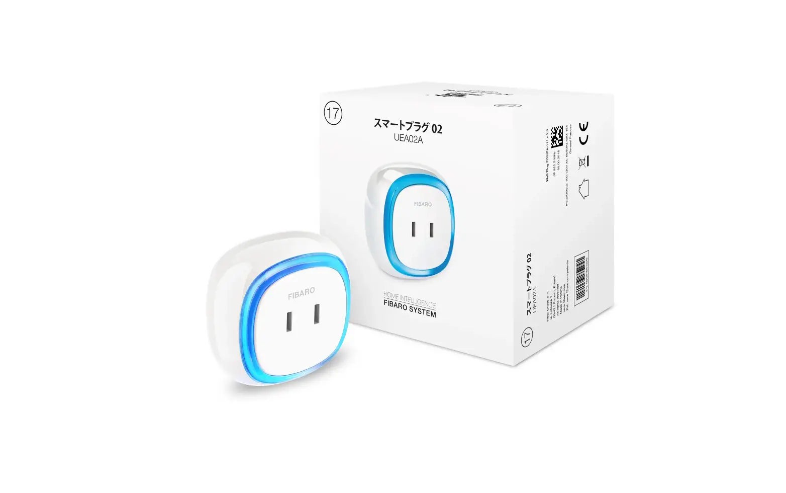

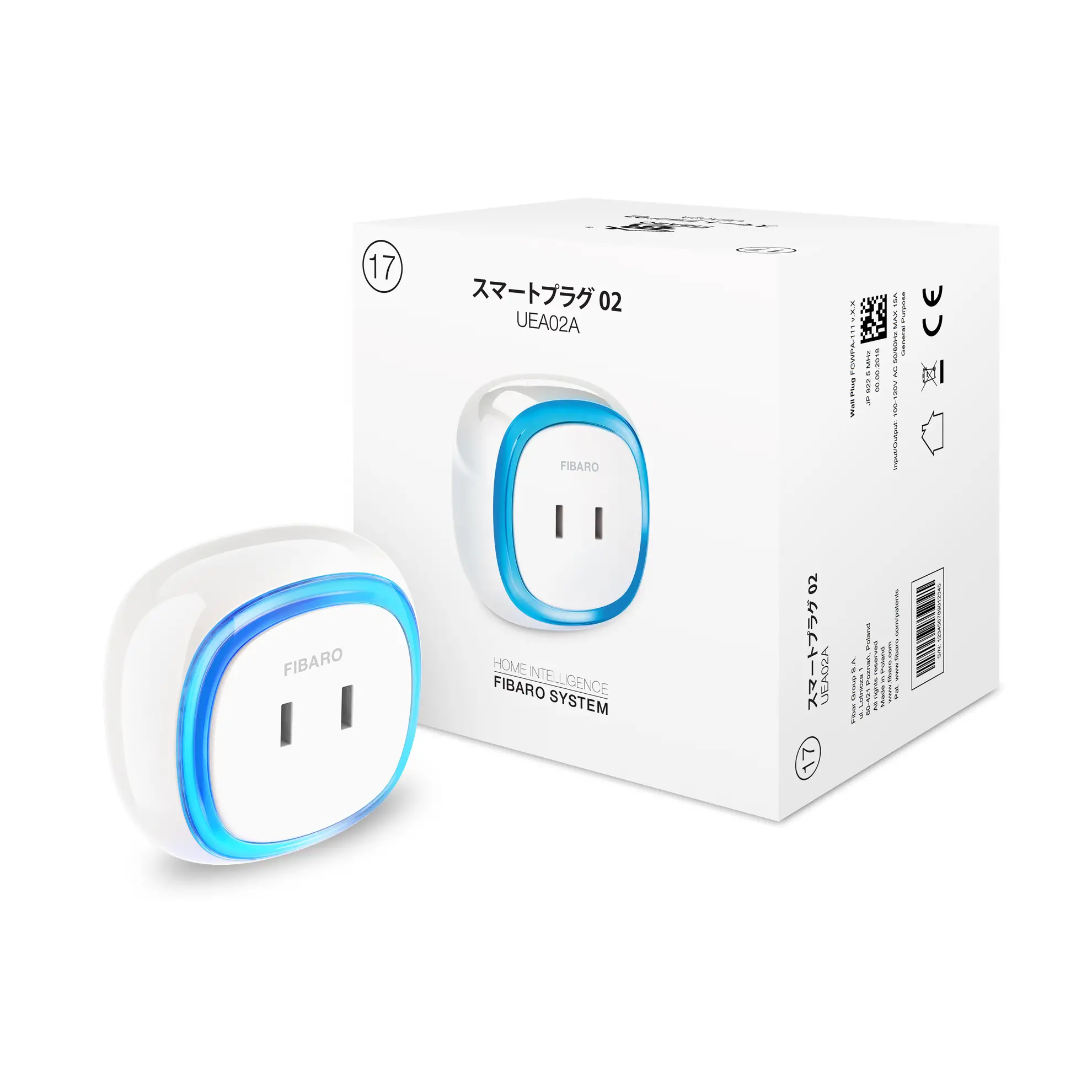
FIBARO
Wall Plug JP
SKU: FGWPA-111


Quickstart
This is a
secure
On/Off Power Switch
for
Japan.
To run this device please connect it to your mains power supply.
To add this device to your network execute the following action:
To add the device to the Z-Wave network:1.Plug the device into a socket nearby the main Z-Wave controller.2.The LED frame will glow red signaling not being added (reset or remove the device otherwise).3.Set the main controller in (security/non-security) add mode.4.Quickly, triple click the button located on the casing.5.If you are adding in S2 authenticated mode, type in the device pin code (underlined part of the public key available on the device or in the manual).6.Wait for the adding process to end.7.Successful adding will be confirmed by the Z-Wave controllers message
Please refer to the
Manufacturers Manual for more information.
Important safety information
Please read this manual carefully. Failure to follow the recommendations in this manual may be dangerous or may violate the law.
The manufacturer, importer, distributor and seller shall not be liable for any loss or damage resulting from failure to comply with the instructions in this manual or any other material.
Use this equipment only for its intended purpose. Follow the disposal instructions.
Do not dispose of electronic equipment or batteries in a fire or near open heat sources.
What is Z-Wave?
Z-Wave is the international wireless protocol for communication in the Smart Home. This
device is suited for use in the region mentioned in the Quickstart section.

Z-Wave ensures a reliable communication by reconfirming every message (two-way
communication) and every mains powered node can act as a repeater for other nodes
(meshed network) in case the receiver is not in direct wireless range of the
transmitter.
This device and every other certified Z-Wave device can be used together with any other
certified Z-Wave device regardless of brand and origin as long as both are suited for the
same frequency range.
If a device supports secure communication it will communicate with other devices
secure as long as this device provides the same or a higher level of security.
Otherwise it will automatically turn into a lower level of security to maintain
backward compatibility.
For more information about Z-Wave technology, devices, white papers etc. please refer
to www.z-wave.info.
Product Description
FIBARO Wall Plug is a remotely controlled plug-in switch with the ability to measure power and energy consumption. It uses a LED frame to visualize the current load and operating mode with color changing illumination. FIBARO Wall Plug makes it possible to control electrical devices in a convenient and maintenance-free way. Main features of FIBARO Wall Plug:- Compatible with any Z-Wave or Z-Wave+ Controller.- Supports Z-Wave network Security Modes: S0 with AES-128 encryption and S2 with PRNG-based encryption.- Extremely easy installation – simply plug the device into the mains socket.- Works as a Z-Wave signal repeater.- Active power and energy consumption metering for plugged device.- Current value of the load and operating mode are indicated by the multi-color LED frame.
Prepare for Installation / Reset
Please read the user manual before installing the product.
In order to include (add) a Z-Wave device to a network it must be in factory default
state. Please make sure to reset the device into factory default. You can do this by
performing an Exclusion operation as described below in the manual. Every Z-Wave
controller is able to perform this operation however it is recommended to use the primary
controller of the previous network to make sure the very device is excluded properly
from this network.
Reset to factory default
This device also allows to be reset without any involvement of a Z-Wave controller. This
procedure should only be used when the primary controller is inoperable.
Reset procedure allows to restore the device back to its factory settings, which means all information about the Z-Wave controller and user configuration will be deleted.1.Make sure the device is powered.2.Press and hold the button.3.Wait for the LED frame to glow yellow (3rd menu position).4.Release the button.5.Click the button once to confirm selection.6.After few seconds the device will restart with factory settings, which is signaled with the red frame color.Resetting the device is not the recommend- ed way of removing the device from the Z-Wave network. use reset procedure only if the primary con- troller is missing or inoperable.
Safety Warning for Mains Powered Devices
ATTENTION: only authorized technicians under consideration of the country-specific
installation guidelines/norms may do works with mains power. Prior to the assembly of
the product, the voltage network has to be switched off and ensured against re-switching.
Inclusion/Exclusion
On factory default the device does not belong to any Z-Wave network. The device needs
to be added to an existing wireless network to communicate with the devices of this network.
This process is called Inclusion.
Devices can also be removed from a network. This process is called Exclusion.
Both processes are initiated by the primary controller of the Z-Wave network. This
controller is turned into exclusion respective inclusion mode. Inclusion and Exclusion is
then performed doing a special manual action right on the device.
Inclusion
To add the device to the Z-Wave network:1.Plug the device into a socket nearby the main Z-Wave controller.2.The LED frame will glow red signaling not being added (reset or remove the device otherwise).3.Set the main controller in (security/non-security) add mode.4.Quickly, triple click the button located on the casing.5.If you are adding in S2 authenticated mode, type in the device pin code (underlined part of the public key available on the device or in the manual).6.Wait for the adding process to end.7.Successful adding will be confirmed by the Z-Wave controllers message
Exclusion
To remove the device from the Z-Wave network:1.Plug the device into a socket nearby the main Z-Wave controller.2.The LED frame will glow green signaling being added (removing is not necessary otherwise).3.Set the main controller into remove mode.4.Quickly, triple click the button located on the casing.5.Wait for the removing process to end.6.Successful removing will be confirmed by the Z-Wave controllers message.
Communication to a Sleeping device (Wakeup)
This device is battery operated and turned into deep sleep state most of the time
to save battery life time. Communication with the device is limited. In order to
communicate with the device, a static controller C is needed in the network.
This controller will maintain a mailbox for the battery operated devices and store
commands that can not be received during deep sleep state. Without such a controller,
communication may become impossible and/or the battery life time is significantly
decreased.
This device will wakeup regularly and announce the wakeup
state by sending out a so called Wakeup Notification. The controller can then
empty the mailbox. Therefore, the device needs to be configured with the desired
wakeup interval and the node ID of the controller. If the device was included by
a static controller this controller will usually perform all necessary
configurations. The wakeup interval is a tradeoff between maximal battery
life time and the desired responses of the device. To wakeup the device please perform
the following action:
FIBARO Wall Plug is powered with mains voltage so it is always awake.
Quick trouble shooting
Here are a few hints for network installation if things dont work as expected.
- Make sure a device is in factory reset state before including. In doubt exclude before include.
- If inclusion still fails, check if both devices use the same frequency.
- Remove all dead devices from associations. Otherwise you will see severe delays.
- Never use sleeping battery devices without a central controller.
- Dont poll FLIRS devices.
- Make sure to have enough mains powered device to benefit from the meshing
Association – one device controls an other device
Z-Wave devices control other Z-Wave devices. The relationship between one device
controlling another device is called association. In order to control a different
device, the controlling device needs to maintain a list of devices that will receive
controlling commands. These lists are called association groups and they are always
related to certain events (e.g. button pressed, sensor triggers, …). In case
the event happens all devices stored in the respective association group will
receive the same wireless command wireless command, typically a ‘Basic Set’ Command.
Association Groups:
Group NumberMaximum NodesDescription
| 1 | 1 | Lifeline reports the device status and allows for assigning single device only (main controller by default). |
| 2 | 5 | On/Off (Button) devices in this group will be switched on or off when relay status is changed using the button (uses Basic command class). |
| 3 | 5 | On/Off (Plug power) devices in this group will be switched on or off depending on the current load of plugged device (uses Basic command class). |
Configuration Parameters
Z-Wave products are supposed to work out of the box after inclusion, however
certain configuration can adapt the function better to user needs or unlock further
enhanced features.
IMPORTANT: Controllers may only allow configuring
signed values. In order to set values in the range 128 … 255 the value sent in
the application shall be the desired value minus 256. For example: To set a
parameter to 200 it may be needed to set a value of 200 minus 256 = minus 56.
In case of a two byte value the same logic applies: Values greater than 32768 may
needed to be given as negative values too.
Parameter 11: Power reporting
This parameter determines the minimum percentage change in active power consumption (in relation to the previously reported) that will result in sending new power report.
Size: 1 Byte, Default Value: 0
SettingDescription
| 0 | power reports inactive |
| 1 – 100 | power change in percent |
Parameter 12: Energy reporting threshold
This parameter determines the minimum change in energy consumption (in relation to the previously reported) that will result in sending a new report.
Size: 2 Byte, Default Value: 0
SettingDescription
| 0 | energy reports inactive |
| 1 – 500 | (0.01-5kWh, step 0.01kWh) – threshold |
Parameter 13: Periodic power reporting
This parameter defines time period between independent reports sent when changes in power load have not been recorded or if changes are insignificant. By default reports are sent every hour.
Size: 2 Byte, Default Value: 1800
SettingDescription
| 0 | periodic reports inactive |
| 30 – 32400 | (in seconds) |
Parameter 14: Periodic energy reporting
This parameter defines time period between independent reports sent when changes in power load have not been recorded or if changes are insignificant. By default reports are sent every hour.
Size: 2 Byte, Default Value: 1800
SettingDescription
| 0 | periodic reports inactive |
| 30 – 32400 | (in seconds) |
Parameter 15: Measuring energy consumed by the Wall Plug itself
This parameter determines whether power metering should include the amount of power consumed by the Wall Plug itself. Results are being added to the value of power consumed by controlled device.
Size: 1 Byte, Default Value: 0
SettingDescription
| 0 | function inactive |
| 1 | function active |
Parameter 2: Remember device status before the power failure
This parameter determines how the Wall Plug will react in the event of power supply failure (e.g. power outage or taking out from the electrical outlet). After the power supply is back on, the Wall Plug can be restored to previous state or remain switched off.
Size: 1 Byte, Default Value: 1
SettingDescription
| 0 | device remains switched off |
| 1 | device restores the state from before the power failure |
Parameter 21: UP value – On/Off (Power) association group (3)
Upper power threshold, used in parameter 23. UP value cannot be lower than a value specified in parameter 22.
Size: 2 Byte, Default Value: 500
SettingDescription
| 100 – 18000 | (10.0-1800.0W, step 0.1W) |
Parameter 22: DOWN value – On/Off (Power) association group (3)
Lower power threshold, used in parameter 23. DOWN value cannot be higher than a value specified in parameter 21.
Size: 2 Byte, Default Value: 300
SettingDescription
| 0 – 17900 | (0.0-1790.0W, step 0.1W) |
Parameter 23: Controlling On/Off (Power) association group (3)
This parameter defines the way that 3rd association group devices are controlled. Depends on the actual measured power (according to parameters 21 and 22 settings).
Size: 1 Byte, Default Value: 3
SettingDescription
| 1 | send frame (with value set in parameter 26) only if power exceeded value of parameter 21 |
| 2 | send frame (with value set in parameter 27) only if power dropped below value of parameter 22 |
| 3 | send frame in both cases |
The value of BASIC SET command frame sent to the devices associated in 2nd group On/Off (Button) when turning the device ON using the button.
Size: 2 Byte, Default Value: 255
SettingDescription
| 0 | turning off associated devices |
| 1 – 99 | forcing level of associated devices |
| 255 | setting associated devices to the last remembered state or turning them on |
The value of BASIC SET command frame sent to the devices associated in 2nd group On/Off (Button) when turning the device OFF using the button.
Size: 1 Byte, Default Value: 0
SettingDescription
| 0 | turning off associated devices |
| 1 – 99 | forcing level of associated devices |
| 255 | setting associated devices to the last remembered state or turning them on |
Parameter 26: THRESHOLD UP value – On/Off (Power) association group (3)
The value of BASIC SET command frame sent to the devices associated in 3rd group On/Off (Power) if power exceeded value of parameter 21.
Size: 2 Byte, Default Value: 255
SettingDescription
| 0 | turning off associated devices |
| 1 – 99 | forcing level of associated devices |
| 255 | setting associated devices to the last remembered state or turning them on |
Parameter 27: THRESHOLD DOWN value – On/Off (Power) association group (3)
The value of BASIC SET command frame sent to the devices associated in 3rd group On/Off (Power) if power dropped below value of parameter 22.
Size: 2 Byte, Default Value: 0
SettingDescription
| 0 | turning off associated devices |
| 1 – 99 | forcing level of associated devices |
| 255 | setting associated devices to the last remembered state or turning them on |
Parameter 3: Overload safety switch
This function allows to turn off the controlled device in case of exceeding the defined power.Controlled device can be turned back on via button or sending a control frame. By default this function is inactive.
Size: 2 Byte, Default Value: 0
SettingDescription
| 0 | function inactive |
| 10 – 18000 | 1.0-1800.0W, step 0.1W) – power threshold |
Parameter 30: Active alarms
Define Z-Wave network alarms to which the Wall Plug will respond.
Size: 1 Byte, Default Value: 63
SettingDescription
| 1 | general alarm |
| 2 | smoke alarm |
| 4 | CO alarm |
| 8 | CO2 alarm |
| 16 | high temperature alarm |
| 32 | flood alarm |
| 64 | all |
Parameter 31: Response to alarm frames
This parameter defines how the Wall Plug will respond to alarms (devicesstatus change).In case of values 1 or 2 the Wall Plug is operating normally and LED frame signals an alarm through time defined in parameter 32 or until the alarm is canceled.In case of values 5 to 50 the Wall Plug does not report status change, power changes, ignores BASIC SET command frames. After time defined in parameter 32 or after the alarm cancellation, connected device is set to the previous state.
Size: 1 Byte, Default Value: 0
SettingDescription
| 0 | no reaction |
| 1 | turn connected device on |
| 2 | turn connected device off |
| 5 – 50 | (0.5-5.0s, step 0.1s) – cyclically change device state with set period |
Parameter 32: Alarm state duration
This parameter specifies the duration of alarm state. If a device sending an alarm frame through the Z-Wave network sets alarm duration as well, this settings are ignored.
Size: 2 Byte, Default Value: 600
SettingDescription
| 1 – 32400 | (in seconds) |
Parameter 40: Power load for violet color
This parameter determines maximum active power value, which when exceeded, causes the LED frame to flash violet. Function is active only when parameter 41 is set to 1 or 2.
Size: 2 Byte, Default Value: 18000
SettingDescription
| 1000 – 18000 | (100.0-1800.0W, step 0.1W) |
Parameter 41: LED frame color when controlled device is on
When set to 1 or 2, LED frame color will change depending on active power and parameter 40. Other colors are set permanently and do not depend on powerconsumption.
Size: 1 Byte, Default Value: 1
SettingDescription
| 0 | illumination turned off completely |
| 1 | color changes smoothly depending on active power |
| 2 | color changes in steps depending on active power |
| 3 | white |
| 4 | red |
| 5 | green |
| 6 | blue |
| 7 | yellow |
| 8 | cyan |
| 9 | magenta |
Parameter 42: LED frame color when controlled device is off
This parameter defines the illumination color after turning off.
Size: 1 Byte, Default Value: 0
SettingDescription
| 0 | illumination turned off completely |
| 1 | LED frame is illuminated with a color corresponding to the last measured power, before the controlled device was turned off |
| 3 | white |
| 4 | red |
| 5 | green |
| 6 | blue |
| 7 | yellow |
| 8 | cyan |
| 9 | magenta |
Parameter 43: LED frame color at the Z-Wave network alarm detection
This parameter defines the illumination color in case of Z-Wave alarm.
Size: 1 Byte, Default Value: 2
SettingDescription
| 0 | illumination turned off completely |
| 1 | no change in color. LED frame color is determined by settings of parameters 41 or 42 |
| 2 | LED frame flashes red/blue/white |
| 3 | white |
| 4 | red |
| 5 | green |
| 6 | blue |
| 7 | yellow |
| 8 | cyan |
| 9 | magenta |
Technical Data
| Hardware Platform | ZM5101 |
| Device Type | On/Off Power Switch |
| Network Operation | Always On Slave |
| Firmware Version | HW: 1 FW: 4.02:04.02 |
| Z-Wave Version | 6.71.01 |
| Certification ID | ZC10-19016342 |
| Z-Wave Product Id | 0x010F.0x1701.0xA000 |
| Color | White |
| Loads Controlled | 3 |
| Firmware Updatable | Updatable by Consumer by RF |
| Sensors | Power |
| Supported Notification Types | Power ManagementSystem |
| Supported Meter Type | Electric Energy |
| Electric Load Type | IncandescentInductive (e.g. Motor) |
| Security V2 | S2_UNAUTHENTICATED ,S2_AUTHENTICATED |
| Frequency | XXfrequency |
| Maximum transmission power | XXantenna |
Supported Command Classes
- Application Status
- Association Grp Info V2
- Association V2
- Basic
- Configuration
- Crc 16 Encap
- Device Reset Locally
- Firmware Update Md V4
- Manufacturer Specific V2
- Meter V3
- Multi Channel Association V3
- Notification V8
- Powerlevel
- Protection V2
- Security
- Security 2
- Supervision
- Switch Binary
- Transport Service V2
- Version V2
- Zwaveplus Info V2
Controlled Command Classes
- Basic
Explanation of Z-Wave specific terms
- Controller — is a Z-Wave device with capabilities to manage the network.
Controllers are typically Gateways,Remote Controls or battery operated wall controllers. - Slave — is a Z-Wave device without capabilities to manage the network.
Slaves can be sensors, actuators and even remote controls. - Primary Controller — is the central organizer of the network. It must be
a controller. There can be only one primary controller in a Z-Wave network. - Inclusion — is the process of adding new Z-Wave devices into a network.
- Exclusion — is the process of removing Z-Wave devices from the network.
- Association — is a control relationship between a controlling device and
a controlled device. - Wakeup Notification — is a special wireless message issued by a Z-Wave
device to announces that is able to communicate. - Node Information Frame — is a special wireless message issued by a
Z-Wave device to announce its capabilities and functions.


