![]() User manual
User manual
X-Pro D140 Réf. 40090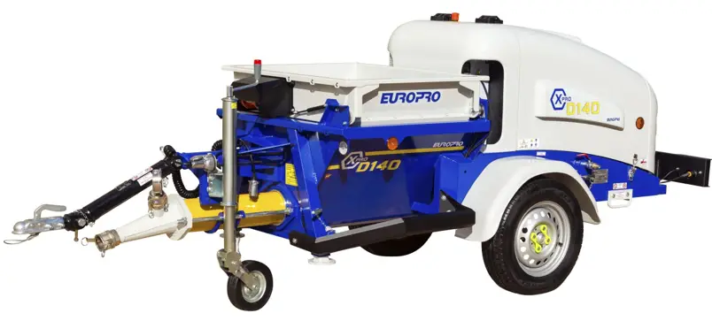
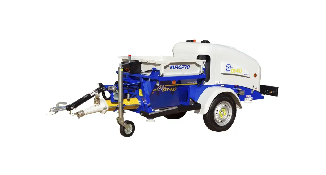
X-Pro D140 Liquid Screed Machine
You just acquired one of our machines and all the team of Europe Projection thanks you for the confidence you have granted us.
Manufacturer of professional equipments for paint and fillers, we have put our know-how for 25 years at the service of the users of our machines.
Our technical & commercial team is at your disposal for any further information you may need about the machine you just acquired.
EUROPE PROJECTION
228, avenue Olivier Perroy
13790 ROUSSET
Tél : +33 (0)4 42 29 08 96
[email protected]
USER MANUAL
1.1. IMPORTANCE OF THE MANUAL
This manual is a key part for the use of your machine. It summarizes the procedures of starting-up, cleaning and maintenance of the device and also the safety instructions you need to observe.
Read carefully all the working and safety instructions and the warnings included in this manual before starting your machine.
Most of the accidents are caused by the non-compliance of the safety standards and rules.
This manual must be kept near the machine, within reach of the user and held in good condition until the final destruction of the machine.
In case of loss or deterioration of the manual, you can ask the machine manufacturer mentioned on page 4 for a copy at any moment.
1.2. RECEIVERS OF THE MANUAL
This manual is intended to any staff which will manipulate the machine :
– people in charge of the transport of the machine
– people in charge of the use of the machine
– people in charge of the cleaning and maintenance of the machine
– people in charge of the final destruction of the machine
WARNING
2.1. SAFETY
Using the machine in an incorrect way or in non-compliance of the safety instructions indicated in this manual can cause death or serious injuries.
Read carefully all the working and safety instructions and the warnings contained in this manual before starting your machine.
 Respect all the safety standards before running the equipment.
- Use the equipment only for the applications specified in the manual.
- Always remain alert when using the equipment.
- Transport the machine using the handles or the appropriate grips.
- During the breaks, disconnect electrically the machine.
- Run the equipment to its nominal voltage.
- Let at least 50 cm of free space between the equipment and any obstacle so that the air flow is not blocked.
- Know how to quickly stop the equipment in case of necessity.
- Never use the equipment while it is running abnormally or it is defective.
- Do not direct a water jet or flammable liquid on the machine.
- Never direct an air jet or product jet on a person or an animal.
- Do not touch warm surfaces of the equipment.
- Always wear adequate body protections (glasses, gloves, overall and mask) and pay attention to long hair.
- Never touch moving parts.
- Do not insert any object or the hands inside the protection grids to avoid any accident or damage to the machine.
- For any outside job, only use appropriate extension cords.
- Maintain the equipment carefully and clean it properly after every use.
- Disconnect the equipment before any intervention.
- Avoid absolutely to unscrew any connection while the machine is under pressure.
- Check the damaged parts.
- Do not clean the plastic parts with solvant.
- In case of needed After-Sale Service, always specify the machine model and its serial number.
- For any replacement of parts, only use genuine parts.
- Do not modify the machine.
- Do not cut or dismantle the protection grids.
- Do not open the electric box.
WORKSPACE
- Maintain the workspace clean and clear.
- Ambient operating temperature must be from -5°C and 35°C.
- Do not use the equipment in a potentially explosive area.
- Do not place any potentially inflammable objects in close proximity to the machine.
- Take away every not qualified person from the working area of the machine, as well as children and animals.
- Do not install the equipment on an inclined surface to avoid the risks of unexpected moves or falls.
HOSES
- Always use hoses and connections adapted to the used product (genuine parts), do not try to fix it.
- Do not walk on the hoses, do not bend them.
- Do not use the hoses to pull the machine.
STORAGE
- Keep the equipment in a clean and clear area in which the temperature does not exceed +35°C.
- After every use, necessarily grease the pump with a mixture of water + storage liquid to avoid it blocking up. The storage of a not greased pump can damage it seriously.
IN CASE OF NECESSITY, WE SAVE OURSELVES THE RIGHT TO MAKE ANY USEFUL MODIFICATION WITHOUT ADVANCED NOTICE.
SAFETY SYSTEMS
This machine has been designed to allow working with the maximum safety.
So safety sensors and emergency stop has been setted on your machine without complicating your work.
We are insisting on your caring to maintain them in good condition and above all not to remove them.
In case of malfunction, please contact immediately your dealer.
HYDRAULIC
This machine is equipped with high pressure hydraulic circuits (200 bar).
The following insctructions are essential for your safety:
- Never tighten a hydraulic connection while the machine is working.
- Never try to wipe an oil drop on a hose or hydraulic component with your finger while the machine is working.
- Take care of the good condition of the plumbing (a damaged or blistered rubber must be changed immediately).
- Check regularly if the circuit does not have any leak.
- In any case, do not touch hydraulic parts (even when the machine is not working) because the components shall be hot and there is a burn risk.
SAFETIES AND PROHIBITIONS
- The hopper grid rising up causes the screw movement stop.
- Emergency stop is located on the machine hood. Do not hesitate to use it if needed, this will immediately stop the motor. To restart the machine after emergency stop button pushed, follow this procedure:
– Put the command buttons in central position.
– Rearm emergency stop.
– Command panel lamps must be lighted-up (green = correct / red = default).
– Engage the starter with the contact key.
– Resume spraying or pumping procedure.
IN CASE OF NECESSITY, WE SAVE OURSELVES THE RIGHT TO MAKE ANY USEFUL MODIFICATION WITHOUT ADVANCED NOTICE.![]() 2.2. TRANSPORT
2.2. TRANSPORT
Only are exempted from the obligation of brakes the only trailers under the double condition that their total weight authorized in load does not exceed 750 kg nor half of the pure weight of the truck tractor.
- This machine was the object of a road homolagation (n°e2*2007/46/0673). As such, it must be registered and can be thus dragged normally on the road network.
- The adjustable jockey wheel easily allows you to fix the helm to the harness of your vehicle.
- The adjustable helm gives you the possibility of adjusting the machine horizontally.
- An electric cable provided with a grip allows you to link the device of lighting of the trailer with the tractor truck.
- A cable of break allows to bind the device of harness of your vehicle with the machine in case of hanging problem of the helm during a travel.
It is imperative to collide this cable on the harness of the vehicle.
![]() X-Pro D140 is not a transport trailer, it is strictly forbidden to transport people or products related to the application of the machine.
X-Pro D140 is not a transport trailer, it is strictly forbidden to transport people or products related to the application of the machine.
Before any road travel:
- Check the pressure of the pneumatics which has to be 2.8 bar max.
- Check the tightening of the nuts of wheels.
- Check the tightening of the nuts of the articulated helm and the presence of pins.
- Clean reflectors.
- Clean and check the functioning of the device of lighting.
- Collide the cable of break.
2.3. END OF LIFE OF THE PRODUCT![]() At its end-of-life, the machine must not be eliminated with the other household waste. The uncontrolled elimination of waste can harm the environment or human health. Individuals are invited to contact the distributor which sold them the product or to inquire with their city hall to know where and how to get rid of the product so it can be recycled while respecting the environment.
At its end-of-life, the machine must not be eliminated with the other household waste. The uncontrolled elimination of waste can harm the environment or human health. Individuals are invited to contact the distributor which sold them the product or to inquire with their city hall to know where and how to get rid of the product so it can be recycled while respecting the environment.
For any further information, please contact our hotline +33 4 42 29 08 96 or [email protected].
YOUR MACHINE
3.1. DESCRIPTION
Thermal engine machine for spraying shotcrete or pumping products such as liquid screed.
Made in Spain, it is equipped with a button control panel for simplified use, an automatic accelerator, motor and hydraulic pump with adjustable flow-rate.
The safety devices comply with the standards in place and the hydraulic circuits are protected against possible blockages of the rotating elements. An air cooler ensures that the oil temperature is maintained within the correct range.
3.2. TECHNICAL CHARACTERISTICS
| Motor | Kohler KDW 1404 |
| Motor power | 17,9 kW |
| Oil | 5W40 synthetic |
| Fuel | Diesel |
| Diesel tank | 29 L |
| Cooling | liquid |
| Speed of rotation | 2600 RPM |
| Number of cylinders | 4 |
| Consumption | 6,2 L/h |
| Hydraulic system | 40 L |
| Engine monitoring panel | complete |
| Hydraulic controls | electrical/manual |
| Pump speed setting | manual |
| Automatic accelerator control | electrical/automatic |
| Hopper tank capacity | 218 L |
| Tank drain plug | yes |
| Variable flow | up to 14 m3/h |
| Hydraulic pressure | from 0 to 140 bar |
| Pump pressure | from 0 to 30 bar |
| Maximum grain size | up to 10 mm |
| Pump | 60R12 |
| Pump reverse operation | yes |
| HP washer max pressure | 140 bar |
| HP washer flow-rate | 11 L/min |
| Overall length with tow bar | 3,66 m |
| Overall length without tow bar | 3,28 m |
| Overall width | 1,24 m |
| Height at the highest point | 1,28 m |
| Weight when full with oil and diesel | 720 kg |
| Delivery height | 80 m |
| Max. hose length | 120 m |
|
Delivered with | – a Ø50 x 20 m hose – a 22 m wired remote control – two cleaning balls Ø50 – a grease pump with a grease cartridge – a complete high pressure washer lance – a 10 m high pressure washer hose – a storage carry-case |
3.3. IDENTIFICATION OF THE COMPONENTS
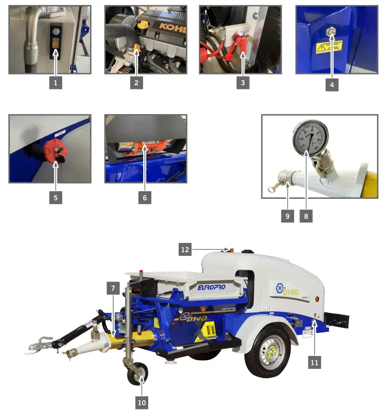
| 1 | Hydraulic oil level |
| 2 | Engine oil level |
| 3 | Electric circuit breaker |
| 4 | Motor flange lubricator |
| 5 | Diesel tank cap |
| 6 | Hopper vibrator |
| 7 | Adjustable pump |
| 8 | Product pressure control manometer |
| 9 | Pump outlet |
| 10 | Jockey wheel |
| 11 | Hood clips |
| 12 | Emergency stop |
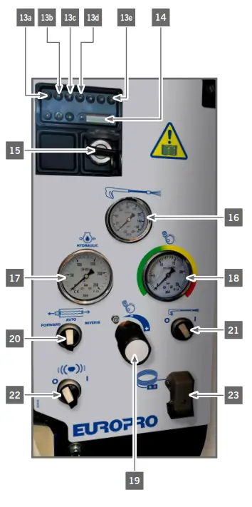
| 13 | Diesel engine display |
| 13a | Low fuel level (diesel). |
| 13b | Battery (lights up when the alternator does not charge the battery). |
| 13c | Oil (lights up when oil pressure is insufficient). |
| 13d | Cooling liquid (lights up when the maximum operating temperature is reached and causes the engine to stop). |
| 13e | Pre-heating (switches off when the pre-heating temperature is reached). |
| 14 | Hour meter |
| 15 | Switching on the machine and starting the engine |
| 16 | Washer circuit pressure manometer Maximum pressure 150 bar. |
| 17 | Screw hopper circuit pressure manometer Maximum pressure 250 bar. |
| 18 | Flow rate adjustment indicator Maximum pressure 25 bar. |
| 19 | Flow rate adjustment knob To be adjusted according to the type of product used. |
| 20 | Product pump rotation control switch Reverse: right position with spring return to the centre. Stop: centre position. Forward: left position maintained. |
| 21 | HP washer switch: On (right position) / Off (left position) |
| 22 | Hopper vibrator control |
| 23 | Remote control plug |
USE OF THE MACHINE
4.1. MACHINE PREREQUISITES
- Check the hydraulic oil level (1) and complete if necessary.
- Check engine oil level (2) and complete if necessary.
- Check the lubrication of the motor flange of the hopper (4).
![]() There must be no foreign objects into the hopper (trowel, tools, etc.).
There must be no foreign objects into the hopper (trowel, tools, etc.).
- After a prolonged standstill, it is possible that the pump might be blocked. If this is the case, alternately turn the pump forwards and backwards for 3 second sequences using the switch (20). As soon as the engine starts to turn normally, the pump is unblocked.
![]() Never use petroleum-based products in the pump, as they may damage it.
Never use petroleum-based products in the pump, as they may damage it.
Never run the pump without water or product.![]() The machine is delivered with a 20 m hose length, this length is optimized to obtain the best output in normal conditions of use.
The machine is delivered with a 20 m hose length, this length is optimized to obtain the best output in normal conditions of use.
If a longer length is used, it is essential to check the correct operation of the whole unit.
Increasing the length of the hose may result in a reduction of the flow rate to zero (too much pressure drop in the hose).
The pressure drop in the hoses is proportional to their length and to the viscosity of the product. In some cases, it will be necessary to use a pump that generates a higher pressure to compensate for this loss. Whenever possible, a dilution of the product and a higher pump pressure will allow a better flow in the hoses.
4.2. MACHINE STARTING UP![]() Before using the machine, the drawbar must be completely removed.
Before using the machine, the drawbar must be completely removed.
Leaving the drawbar in place can cause damage to the machine chassis.
- Place the machine horizontally by lowering or raising the jockey wheel (10) so that the machine is stable and level.
- Unlock the emergency stop (12) on top of the fixed polyester hood.
- Place the contact key in the ON position. The lights should light up, otherwise check that the circuit breaker (3) located under the hood, above the battery, is in the ON position.
- Wait until the preheating indicator light (13e) turns off and then activate the engine starter by turning the contact key (15).
- Let the engine run for 5 to 10 minutes to warm up before continuing work.
- Fill the hopper with approx. 30 litres of water.
- Connect the remote control cable to the socket (23) if necessary for the work to be done.
- Connect the product hose to the pump outlet (9).
- Turn the selector (20) to the left so that the pump turns to the FORWARD position.
- Run water through the hose and then empty the hose.
- Prepare a mixture of water and liquid cement and pour it into the hose.
- Empty the remaining water in the hopper by opening the plug for this purpose.
- Pour the product to be used into the hopper. The machine is now ready to work.
- During use, use the control (19) to adjust the product flow rate.
![]() Never run the screw without product or water.
Never run the screw without product or water.![]() The screw rotation control handle has a preferential direction characterized by a held position. Reverse rotation is possible by holding the handle manually in the RIGHT position.
The screw rotation control handle has a preferential direction characterized by a held position. Reverse rotation is possible by holding the handle manually in the RIGHT position.
PUMP PRESSURE CONTROL :
- Pour water into the tank.
- Connect the control hose to the pump outlet (9).
- Connect the machine outlet adapter, then the pressure controller (ref. 13202 and 13044 optional and not supplied).
- Set the flow rate to maximum.
- Turn the switch (20). When water comes out, close the valve of the pressure controller and read the value on the manometer (8) which must be set between 12 and 15 bar.
- To adjust the pump pressure, tighten or loosen the screws on the pump.
4.3. HIGH PRESSURE WASHER PREREQUISITES
- Control is carried out by the HP WASHER selector (21).
- The high pressure cleaner kit includes:
– the quick coupler for connecting the water supply
– the 10 m pressure hose, the gun and the lance - Before switching on the washer, check that the water supply hose as well as the pressure hose and the complete lance are connected.
![]() It is essential for the proper functioning and longevity of the washer that it never operates without water. Therefore, before starting the washer, it is imperative to open the water supply valve of the supply source and check that there are no knots in the supply hose.
It is essential for the proper functioning and longevity of the washer that it never operates without water. Therefore, before starting the washer, it is imperative to open the water supply valve of the supply source and check that there are no knots in the supply hose.
HOSES CONNECTION :

![]() Remember to clean the suction filter very regularly (at least once a week) to avoid cavitation of the pump. The filter is located just behind the water inlet connection.
Remember to clean the suction filter very regularly (at least once a week) to avoid cavitation of the pump. The filter is located just behind the water inlet connection.
4.4. HIGH PRESSURE WASHER STARTING UP![]() Always wear the appropriate personal protective equipment (goggles, gloves, etc.) so as not to injure yourself during cleaning.
Always wear the appropriate personal protective equipment (goggles, gloves, etc.) so as not to injure yourself during cleaning.![]() This cleaner is dedicated exclusively to the cleaning of the machine.
This cleaner is dedicated exclusively to the cleaning of the machine.
- Move the washer starting swtich to the right position.
- Press the trigger of the cleaning lance and clean the machine.
ONCE THE CLEANING IS COMPLETE:
- Move the washer starting switch to the left position.
- Turn off the water supply at the source and disconnect the supply hose.
- Press the gun on the cleaning lance to release the residual pressure in the high pressure hose.
- Disconnect the high pressure hose.
- Clean the filter behind the water inlet quick coupling.
DEFECTS AND REMEDIES
| n° | Defects | To check | Remedies |
| 1 | Dashboard lights do not illuminate. | The circuit breaker is not engaged. | Check the position of the circuit breaker, turn the key clockwise. |
| The dashboard fuse is out of order. | Change the fuse. | ||
| The battery connections are bad. | Check both battery terminals. Check the presence of grey-green, brush the pods. | ||
| The battery is out of order or not charged. | Contact the nearest technical service, the battery must be changed, pay attention to the polarities. | ||
| The power supply circuit must be swit- ched off somewhere. | Contact Technical Service. | ||
| 2 | Engine does not start when cold | Check for diesel fuel. | Fill up the tank. |
| Check the quality of the fuel. | Drain the tank, clean and refill with qua- lity diesel fuel.Change the filter. | ||
| Check fuel filter. | It must be changed regularly, check the maintenance booklet, change the filter. | ||
| The engine has been switched off. | Re-start the engine with the hand pump (see engine manual) and check the hoses (air inlet). | ||
| Problem with the electrical supply. | See problem 1. | ||
| Diesel solenoid valve. | Check wire on diesel solenoid valve.Check emergency stop. | ||
| Preheating does not work. | Check the 50A reed switch fuse in the dashboard housing. | ||
| I’ve already checked all these points, but it doesn’t change anything. | Contact technical service. | ||
| 3 | Engine does not start when hot | First | See problem 2. |
| The engine safety system prevents starting due to lack of oil pressure. | Check the oil level of the combustion engine (engine cold). | ||
| The safety relay is out of order | Contact technical service. | ||
| The engine oil pressure sensor is out of order. | Contact technical service. | ||
| 4 | The diesel engine smoks white | There is water in the diesel fuel. | Drain the tank, clean and refill with quality diesel fuel.Change the filter. |
| Check the injection / Clean the injection | Contact technical service. | ||
| Cylinder head gasket. | Check the cooling liquid level. | ||
| Check engine oil level and texture (“mayonnaise”). | |||
| 5 | The diesel engine smokes black | Check engine oil level. | If low level contact technical service. |
| Check the injection / Clean the injection | Contact technical service. |
| n° | Defects | To check | Remedies |
| 6 | Hopper screw does not turn | Check the speed control knob. | Increase speed. |
| Check the position of the grid. | Close the grid (see electronic board indicator). | ||
| Check that the security card is working properly. | |||
| Power supply problem. | See Problem No. 1. | ||
| Hydraulic problem. | Contact the technical service. | ||
| 7 | Hopper screw does not stop | Hydraulic problem. | Contact technical service. |
| 8 | The product does not come out at the end of the spray lance | Check that there are no plugs in the product pipes. | Check the consistency of the product.Unclog hoses. |
| Check that the hopper screw rotates properly. | See problem 6. | ||
| Check the pump for wear. | Use the pressure controller at the pump outlet. | ||
| 9 | HP washer does not work | Check the water supply. | The hose must not be pinched and the water valve open. |
| Check the filter for clogging. | Clean the supply filter before each use. | ||
| Hydraulic problem. | Contact a dealer. | ||
CLEANING PROCEDURE
![]() Before unscrewing the hose, make sure it is not under pressure anymore.
Before unscrewing the hose, make sure it is not under pressure anymore.
- Empty the tank to the maximum without adding water inside.
- Clean the tank (remove the drain ball to allow water to drain from the tank, never run water through the full product hose).
- Once the tank is clean, replace the ball.
- Disconnect the product hose and fill the tank with clean water.
- Activate the rotation of the screw to clean the pump.
- Place the cleaning ball in the product outlet (9) and replace the hose.
- Start the machine.
- When the ball comes out of the hose, stop the machine and repeat operations 6 and 7 until water comes out of the hose clean.
![]() The direct projection of water under pressure onto the control panel has to be stopped at the risk of water infiltration. Proceed by simply cleaning with a humid sponge.
The direct projection of water under pressure onto the control panel has to be stopped at the risk of water infiltration. Proceed by simply cleaning with a humid sponge.
MAINTENANCE
![]() Verifications concerning the diesel engine and hydraulic part must always be carried out on a cold machine.
Verifications concerning the diesel engine and hydraulic part must always be carried out on a cold machine.![]() For any work on the diesel engine, refer to the maintenance manual supplied with the machine.
For any work on the diesel engine, refer to the maintenance manual supplied with the machine.
After the first 50 hours of operation:
– Replace the return filter cartridge on the hydraulic tank.
Every 50 hours:
– Check cooling radiator fins for cleanliness.
– Check the hydraulic oil level on the level indicator on the tank and refill with HV46 hydraulic oil if necessary.
– Grease the hopper bearing and the jockey wheel.
– Check the safety devices of the vibrating strainer.
– Check the operation of the emergency stop located on the fixed cover.
Every 125 hours:
– Check the drawbar axle mountings.
– Check the condition of the axle and tyres.
– Check the condition of the clamping screws of the swivel drawbar as well as the pins.
– Check the attachment and proper functioning of the coupling system.
Every 500 hours:
– Replace the return filter cartridge on the hydraulic tank.
Every 1000 hours and/or every year:
– Drain the hydraulic tank, clean the suction strainer and replace the filter cartridge.![]() In order to guarantee a long-lasting operation of the machine, we invite you to contact your dealer for any maintenance intervention. He will carefully carry out the operations and check the various points we recommend.
In order to guarantee a long-lasting operation of the machine, we invite you to contact your dealer for any maintenance intervention. He will carefully carry out the operations and check the various points we recommend.
| Interval in hours of use or months,whichever comes first. | Hours | 50 | 250 | 500 | 750 | 1000 |
| Months | 2 | 12 | 24 | 36 | 48 | |
| Replace engine oil | X | X | X | X | X | |
| Replace oil filter | X | X | X | X | X | |
| Replace diesel filter | X | X | X | X | X | |
| Replace air filter | X | X | X | X | ||
| Replace belts | X | X | ||||
| Replace coolant | X | X | ||||
| Replace cooling hoses | X | |||||
| Replace fuel hoses | X | |||||
| Replace hydraulic oil filter | X | X | X | X | X | |
| Clean hydraulic tank strainer | X | X | X | |||
| Replace hydraulic oil | X | X | ||||
| Replace cleaner oil | X | X | X | X | ||
| Replace timing belt | 4000 hours ou 4 years | |||||
| Adjust valve clearance | X | X | ||||
| Tare and clean injector | X | |||||
| Clean radiator (outside) | X | X | X | X | ||
| Clean radiator (inside) | X | |||||
| Clean fuel tank | X | |||||
| Clean hydraulic tank | X | |||||
| Check tightening of screws and hoses | X | X | X | X | X | |
| Check pump, seals and flectors | At every use | |||||
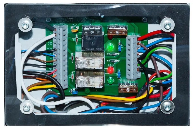
SAFETY CARD RUNNING
8.1. BOTH GREEN LIGHTS ARE ON

| Defect | To check | Remedies |
| Normal running with remote control activated (accelerated engine) | – | – |
8.2. THE LOWER RED LIGHT IS ON
Defect | To check | Remedies |
| Opened hopper strainer | The position of the strainer. | Put the strainer back to its low position. |
| Electrical problem | The circuit must be cut somewhere. | Contact technical service. |
| The safety sensor of the hopper strainer must be incorrectly positioned. | Check the correct alignment of both safety sensor parts of the strainer. | |
| The safety sensor of the hopper strainer does not function. | Contact technical service. | |
| The remote control is defective. |
8.3. ALL FOUR LIGHTS ARE OFF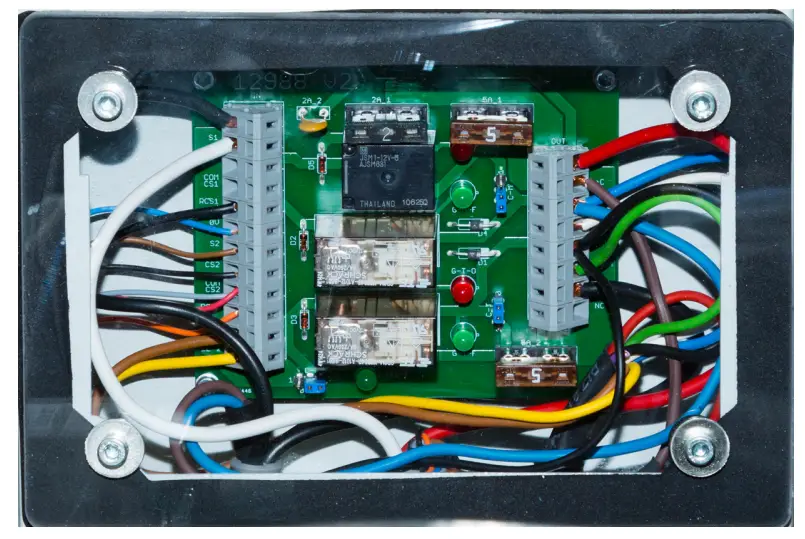
| Defect | To check | Remedies |
| Electrical problem | No engine contact. | Turn the engine start key. |
| The circuit breaker is not engaged. | Check the position of the circuit breaker, turn the key clockwise. | |
| Dashboard fuse is out of order. | Change the fuse. | |
| Battery connections are defective. | Check both battery terminals. Check for the presence of grey green, brush the terminals. | |
| The battery is out of order or not charged. | Contact the nearest technical service, the battery must be changed, pay attention to the polarities. | |
| The power supply circuit must be cut somewhere. | Contact the technical service. | |
| The protective fuses on the card. | Change the faulty fuse. |
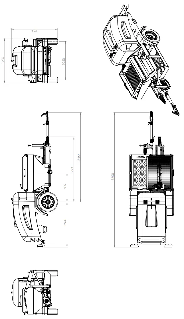
VOLUME SCHEME
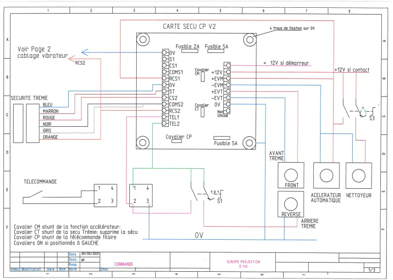
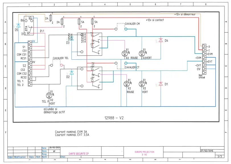
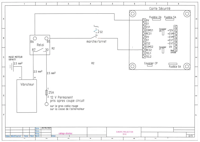
ELECTRICAL SCHEMES
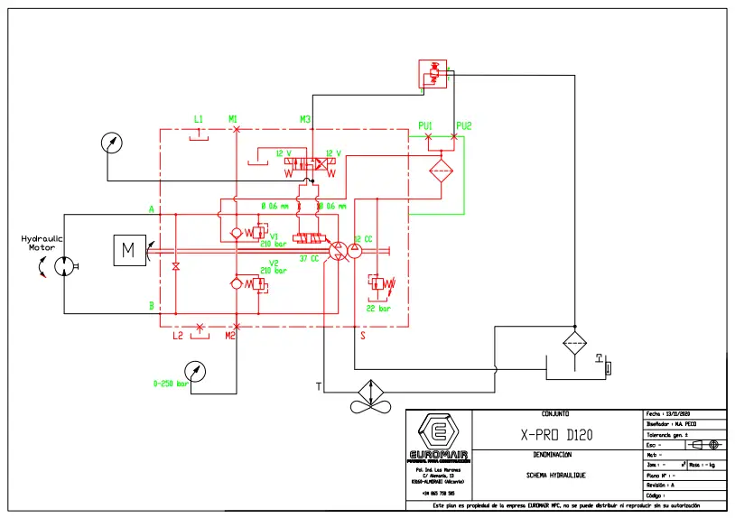
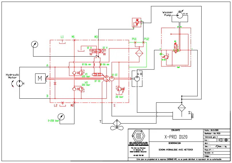
HYDRAULIC SCHEMES
DECLARATION OF CONFORMITY
THE MANUFACTURER : EUROPE PROJECTION 228, avenue Olivier Perroy 13790 ROUSSET
DECLARES THAT THE EQUIPMENT DESIGNATED BELOW:
Trademark: EUROPE PROJECTION
Type: Floor screed machine
Model: X-PRO D140
COMPLIES WITH THE DIRECTIVES:
- Machines 2006/42/CE
- Low voltage 2014/35/UE
- CEM 2014/30/UE
- ROHS 2011/65/UE
- Noise emissions 2005/88/CE
This machine was the object of a road homolagation (n°e2*2007/46/0673). As such, it must be registered and can be thus dragged normally on the road network.
ROUSSET, JANUARY 20th 2023

EUROPE PROJECTION – 228, avenue Olivier Perroy 13790 ROUSSET
Tél : +33 (0)4 42 29 08 96 – Fax : +33 (0)4 42 53 44 36
SAS au capital de 400 000 € – ARCS Aix-en-Provence B 394 961 510 – NAF 2892 Z – Intracom : FR 54 394 961 510
WARRANTY CONDITIONS
Each equipment is delivered inspected and tested.
We exclude any warranty for visible defects, not notified by the customer within 48 hours.
The equipment sold is guaranteed during the manufacturer’s warranty from the date of purchase, as specified on the original proof of purchase, and under the conditions defined by the manufacturer.
This warranty covers any equipment against any manufacturing or material defect, under normal conditions of use. Insofar as the customer is presumed to be a professional of the same field of specialty, this warranty covers only the defect of conception of the equipment rendering it unfit for its use, which could not be detected by a professional buyer.
The defects or deteriorations caused by natural wear, external accident or a modification, use, storage or treatment of the equipment not planned by the manufacturer, nor specified by ourselves, are excluded from any warranty.
Are expressly excluded from the warranty the defects resulting from an improper use, the application of abrasive or corrosive products, an inappropriate installation, the negligence, an insufficient maintenance or cleaning, inappropriate conditions of storage, chemical, electronical or electric influences, any change in the normal process of use.
The following wearing parts are not covered by the warranty (non-exhaustive list): rotors, stators, driving shafts, connecting rods, seals, cleaning balls, spray guns, lance, nozzle, hose, needle kits, cylinders, piston rods, prime/spray valve assy, seal kits, membranes, suction and delivery valves, carding machine vanes, filters, oils, chains and quick-release clip.
The warranty also excludes the equipment on which the serial number was erased or made illegible, on which unauthorized people made attempts of repair, which were totally or partially dismantled. Our equipment are covered by a manufacturer’s warranty (parts and labor) of 12 months following the purchase date by the final customer, without exceeding 24 months from the date of purchase by the client.
This manufacturer’s warranty shall automatically cease if the customer does not resell the equipment within 24 months of its purchase. The cases of exclusion of warranty mentioned in articles above are also applicable to our own equipment.
The manufacturer’s warranty shall always be subject to the presentation of the purchase invoice.
If the defective equipment is covered by the manufacturer’s warranty, it shall be repaired or replaced at our discretion free of charge.
If the defective equipment is not covered by the manufacturer’s warranty, we shall issue a quote for the repair that we shall submit to the customer for approval.
Except as otherwise required by law, this manufacturer’s warranty is exclusive of all other warranties, including the statutory warranty of hidden defects.
In case of intervention of our services on a breakdown caused by the customer or an incident excluded in the conditions referred to above, the costs of repair and transport shall be invoiced to the customer.
We exclude all liability for indirect damages suffered by the customer, such as, but not limited to, loss of income, turnover, loss of profits, loss of image, of any kind whatever.
In all cases, our liability shall be limited to the amount paid by the customer for non-compliant equipment.
Any legal action of the customer against us relating to the warranty of the equipment shall be barred 1 year after the date of discovery of the defect. The customer shall have to prove the date of this discovery.
Request for Warranty
For any request related to the repair of an equipment covered by the manufacturer’s warranty, the customer shall have to fill the warranty form, available on our website, under After-Sale Service.
For a full dossier, the following documents shall have to be attached:
- the purchase invoice of the final user
- pictures of the defective parts of the equipment
- a description of the breakdown
- the quote of labor if the customer is certified by EUROMAIR for repairing the equipment
No invoice of labor shall be taken into account without our prior approval.
Analysis of the breakdown by our technical department
A file number shall be given to the customer and an answer shall be provided within 48 working hours after reception, provided that the request for warranty is considered as full.
In the event the equipment is covered by the manufacturer’s warranty, we shall confirm the warranty to the customer and send him a quote (without price) detailing the parts to be changed and any comments.
Return of replacement parts
Replacement parts must be ordered with a warranty agreement number and will be made available to the customer at our factory.
The conditions of return of the equipment are detailed in our Delivery terms.
In the case of a warranty claim on an on-board component such as a Kohler, Honda or Vanguard engine in a machine manufactured by us, only the manufacturer of the component is able to validate the warranty coverage.
In this case, the request must be addressed directly to the manufacturer of the component or to its nearest authorised representative. The Euromair, Euromair MPC or Mixer service centres may be considered as the manufacturer’s representatives if they are the closest. As this principle also applies to batteries, our supplier Parts Holding Europe, or one of its sister companies, remains your contact for your requests (https://www.partsholdingeurope.com .
FOLLOW-UP OF REVISIONS
The verifications to be made are indicated in paragraph 7. MAINTENANCE.![]() The recommendations given in this manual are indicative and are not a substitute for those recommended by the engine manufacturer.
The recommendations given in this manual are indicative and are not a substitute for those recommended by the engine manufacturer.
For any intervention on the engine, consult the maintenance manual supplied with the machine.
| Date | Signature | Stamp | ||
| Hours of operation | 50 hours | |||
| 250 hours | ||||
| 500 hours | ||||
| 750 hours | ||||
| 1000 hours | ||||
![]() EUROPE PROJECTION – 228, avenue Olivier Perroy 13790 ROUSSET
EUROPE PROJECTION – 228, avenue Olivier Perroy 13790 ROUSSET
Tél : +33 (0)4 42 29 08 96
Fax : +33 (0)4 42 53 44 36
SAS au capital de 400 000 € – RCS Aix-en-Provence B 394 961 510 – NAF 2892 Z – Intracom :
FR 54 394 961 510
More information on www.euromair.com


![Breville 3x Bluicer Pro [bjb815] User Manual](https://static-data1.manualsee.com/1/img/77/17011/2020/12/00-16.jpg "Breville 3x Bluicer Pro [bjb815] User Manual")