citronic PL2000 1U Stereo Power Amplifier
 Introduction
 Introduction
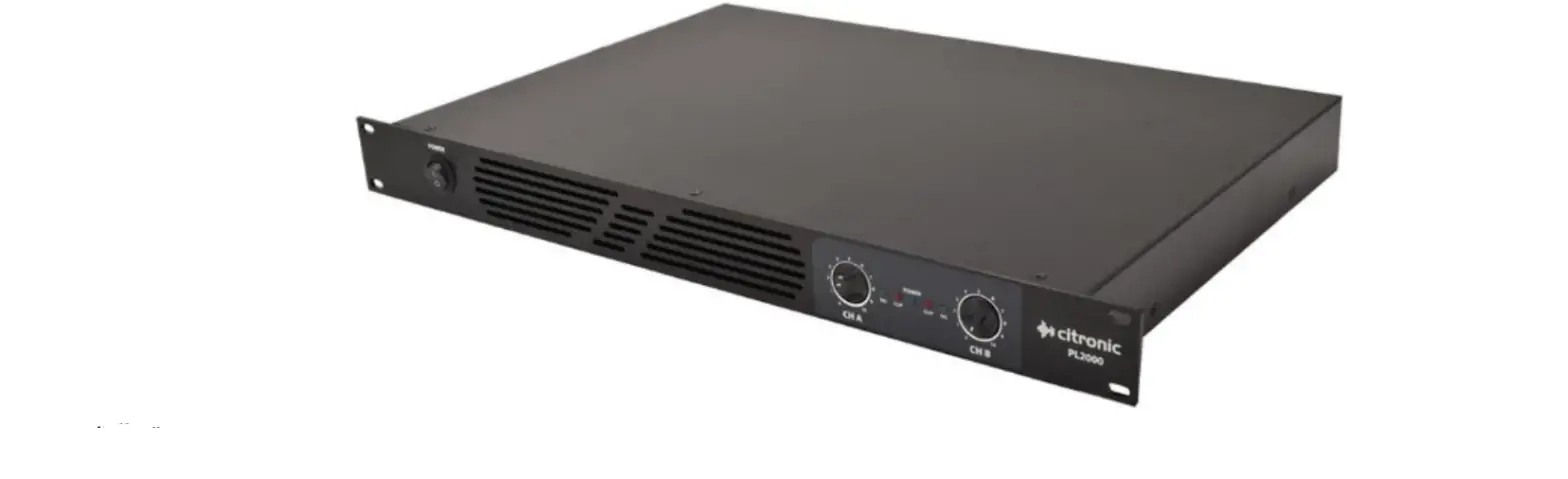
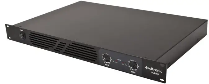
Thank you for choosing the Citronic PL2000 class-D power amplifier as part of your sound reinforcement system. These high output amplifiers are designed to offer high quality, dependable service for mobile and installed systems. Please read this manual fully and follow the instructions to achieve the best results with your new purchase and to avoid damage through misuse.
Warning
To prevent the risk of fire or electric shock, do not expose any of the components to rain or moisture.
If liquids are spilled on the casing, stop using immediately, allow unit to dry out and have checked by qualified personnel before further use. Avoid impact, extreme pressure or heavy vibration to the case
No user serviceable parts inside – Do not open the case – refer all servicing to qualified service personnel.
Safety
- Check for correct mains voltage and condition of IEC lead before connecting to power outlet
- Ensure speaker leads are good condition with no short connections or damaged plugs
- Check impedance of speaker loads do not exceed the minimum stated load for the amplifier
- Do not allow any foreign objects to enter the case or through the ventilation grilles
Placement
- Keep out of direct sunlight and away from heat sources, damp or dusty environments
- When rack-mounting, ensure adequate support for the base of the amplifier and firm fixings for the front
- Ensure adequate air-flow and do not cover cooling vents at the front and rear of the amplifier
- Ensure adequate access to controls and connections
Cleaning
- Use a soft cloth with a neutral detergent to clean the casing as required
- Use a vacuum cleaner to clear ventilation grilles of any dust or debris build-ups
- Do not use strong solvents for cleaning the unit
Front Panel
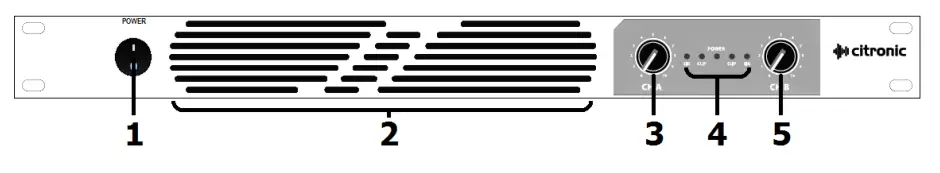
- Power on/off switch
- Cooling vent
- Channel A gain control
- LED indicators
- Channel B gain control
Rear Panel
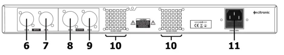
- Channel B input
- Channel A input
- Channel B SPK output
- Channel A SPK output
- Cooling fan vents
- IEC mains power inlet & fuse
Setup
Connect the supplied power lead to the rear IEC inlet of the PL-series amplifier (11) and plug the other end into a mains power socket, ensuring the correct voltage at the outlet.
Ensure that the cooling vents at front and rear (10) are not covered or obstructed in any way with adequate space for airflow through the unit.
Operation
With CH A and CH B volume controls (3, 5) turned fully down (anti-clockwise), switch on the power (1) and the LED POWER indicator will light (4)
Playing the input signal into CH A and CH B inputs (6, 7), gradually increase the CH A and CH B volume controls. The amplified signal should be heard through the speakers and the SIG indicators (4) should respond to the audio output. Increase the volume controls to the required level.
Alongside the SIG indicators are CLIP indicators, which should only light very briefly on the loudest transients or spikes in the audio. If the CLIP LEDs light for more than a fraction of a second at a time, the volume controls should be turned down or input signal will need to be reduced.
Before powering down, turn down the volume controls to avoid loud pops or noises through the speakers.
Specifications
| Power supply | 230Vac 50Hz (IEC) |
| Fuse | T15AL 250V |
| Power RMS @ 8Ω | 2 x 540W |
| Power RMS @ 4Ω | 2 x 1000W |
| Input connections | Combo jack/XLR balanced (L+R) |
| Output connections | SPK (L+R) pin 1+/1- |
| Frequency response | 20Hz – 20kHz (±0.5dB) |
| THD +N | <0.05% |
| Damping factor | 300 |
| S/N ratio (A weighted) : line | 100dB |
| Slew rate | 20V/us |
| Input impedance | 10k Ohms unbalanced, 20k Ohms balanced |
| Output circuit architecture | Class D |
| Protection | Temperature, short circuit, DC, overload |
| Indicators | Power, signal, clip |
| Controls | L+R level, power on/off |
| Dimensions | 482 x 180 x 44mm |
| Weight | 4.0kg |
Disposal: The “Crossed Wheelie Bin” symbol on the product means that the product is classed as Electrical or Electronic equipment and should not be disposed with other household or commercial waste
at the end of its useful life. The goods must be disposed of according to your local council guidelines.


