![]()
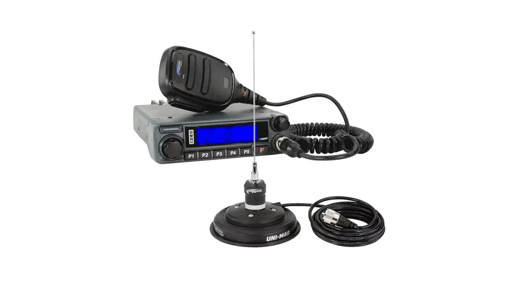
radios GMR45 High Power GMRS Mobile Radio
User Manual 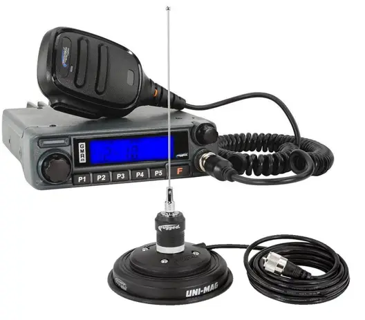
GMR45
USER MANUAL
FCC NOTICE
The GMR45 operates on GMRS (General Mobile Radio Service) frequencies, which require a Federal Communications Commission (FCC) license. You must be licensed prior to operating on channels 1-7, 15-22 or RP15-22 which comprise the GMRS channels of the GMR45. Serious penalties may result from unlicensed use of GMRS channels, in violation of FCC rules, as stipulated in the Communications Act’s Sections 501 and 502 (amended). You will be issued a call sign by the FCC that should be used for station identification when operating your radio on GMRS channels. You should also cooperate by engaging in permissible transmissions only, avoiding channel interference with other GMRS users, and being prudent with the length of your transmission time.
To obtain a license or ask questions about the license application, contact the FCC at 1-888-CALL-FCC or go to the FCC’s website: http://www.fcc.gov and request Form 605.
USER SAFETY INFORMATION
- Do not attempt to configure your radio while driving. · This radio is designed for a 13.8V DC power supply. Do not use a 24V battery to power on the radio.
- Do not place the transceiver in excessively dusty, humid or wet areas, nor unstable surfaces.
- Please keep it away from interference devices (Such as TVs, generators, etc.)
- Do not expose the radio to long periods of direct sunlight or place it close to heating appliances.
- If an abnormal odor or smoke is detected coming from the radio, turn off the power immediately and contact your dealer.
- Do not transmit with high power for extended periods or the radio may overheat.
PACKAGE INCLUDES
- Radio unit x 1
- Hand Mic x 1
- Mobile mounting bracket x 1
- DC power cable with fuse holder x 1
- Screw packs x 1
- Protection fuses x 1
MAIN FEATURES
Go Further with our industry-leading 45-watt GMR45 mobile radio. More wattage equals more power and range, giving you the ability to transmit long distances when it matters. Easily connect to the intercom, headset, or any 5-pin accessory with the built-in Rugged Ready pigtail cable! Loaded with channels and features, the GMR45 is ideal for installation into your vehicle or set up at base camp.
FEATURES:
- 45 Watt Radio
- 8 Repeater Channels
- 15 GMRS Channels (1-7 & 15-22)
- Easily connect to the intercom, headset, or any 5-pin accessory with the built-in Rugged Ready pigtail cable!
- Battery Voltage Display
- Adjustable Squelch
- Keypad Lock
- External Speaker Port
- Clear Backlit Display
- Channel Scan Mode
- Dual-Tone Multi-Frequency (DTMF)*
*Enabled via software available from RT Systems. 6
INITIAL INSTALLATION
MOBILE INSTALLATION
Mobile Installation: To install the radio select a safe and convenient location inside your vehicle that minimizes danger to your passengers and yourself while the vehicle is in motion. Consider installing the unit at an appropriate position so that knees or legs will not strike it during sudden braking of your vehicle. Try to pick a well-ventilated location that is shielded from direct sunlight.
Caution: Extreme care should be exercised when drilling into the dash to avoid damage to under-dash components.
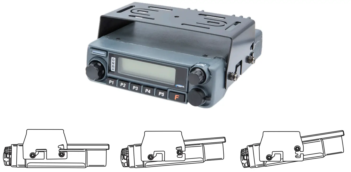
1. Install the mounting bracket in the vehicle using the supplied self-tapping screws and flat washers.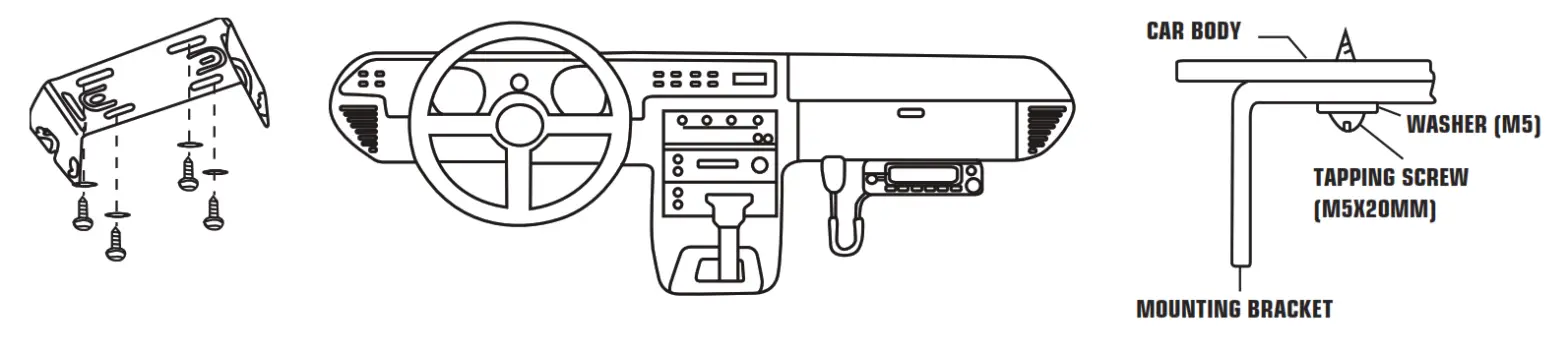 2. Position the radio, then insert and tighten the supplied hex/Phillips screws.
- Determine the appropriate angle of the radio using the 3 screw hole positions on the side of the mounting bracket.
- Double-check that all screws are tightened to prevent vehicle vibration from loosening the bracket or radio.

DC POWER CABLE CONNECTION
The vehicle battery must have a nominal rating of 12V. Never connect the radio to a 24V battery. Be sure to use a 12V vehicle battery that has sufficient current capacity. If the current to the radio is insufficient the display may darken during transmission or transmitting output power may drop dramatically.
- Route the DC power cable supplied with the radio directly to the vehicle’s battery terminals using the shortest path from the radio. We suggest you do not use the cigarette lighter socket as some cigarette lighter sockets introduce an unacceptable voltage drop. The entire length of the cable must be dressed so it is isolated from heat, moisture, and the engine secondary (high voltage) ignition system/cables.
- Confirm the correct polarity of the connections, then attach the power cable to the battery terminals: Red connects to the positive (+) terminal and black connects to the negative (-) terminal.
- Connect the DC power cable to the radio’s power supply connector. Press the connectors firmly together until the locking tab clicks.
REPLACING FUSES
If the fuse blows, determine the cause then correct the problem. After the problem is resolved replace the fuse. If newly installed fuses continue to blow, disconnect the power cable and contact Rugged Radios for assistance. Only use fuses of the specified type and rating otherwise the radio could be damaged.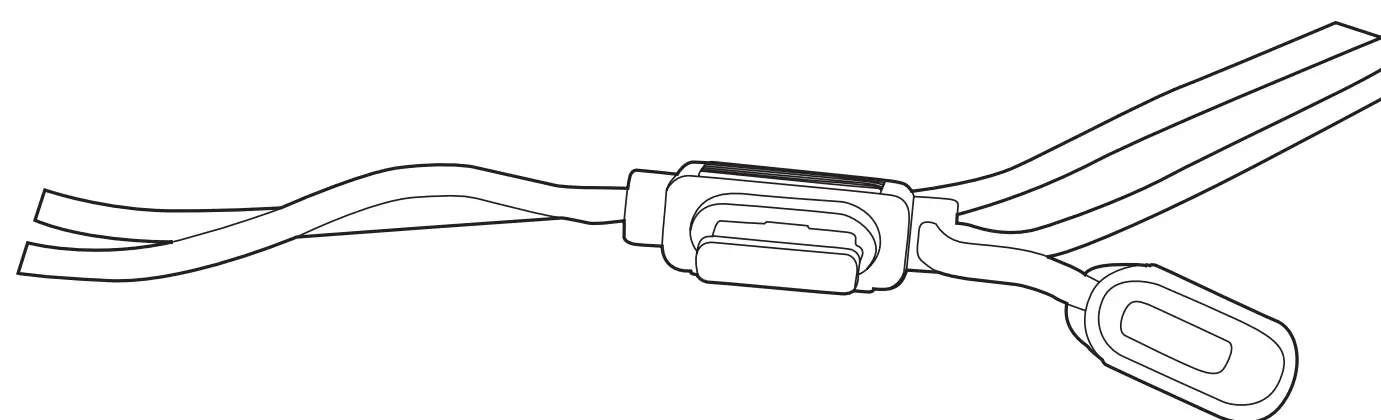
Fuse Location | Fuse Current Rating |
| Transceiver | 15A |
| Supplied accessory DC power cable | 20A |
Note: If you use the radio for a long period when the vehicle battery is not fully charged or when the engine is OFF, the battery may become discharged and will not have sufficient reserves to start the vehicle. Avoid using the radio in these conditions.
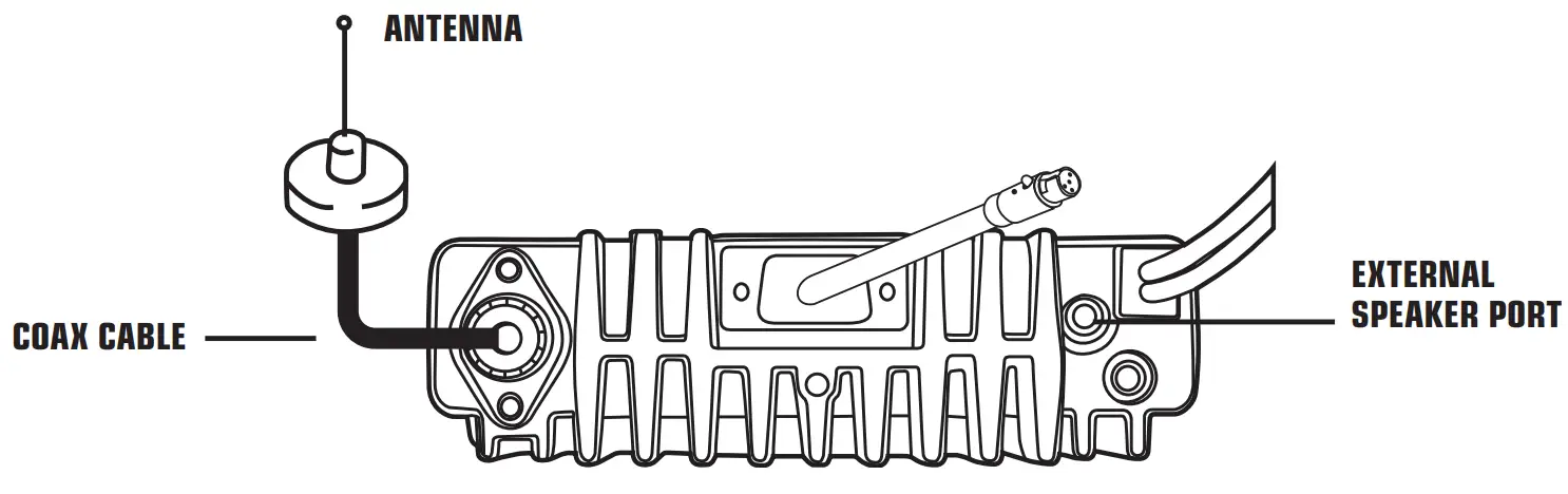
ANTENNA CONNECTION
Before operating, install an efficient well-tuned antenna. The success of your installation will depend largely on the type of antenna and its correct installation. The radio can give excellent results if the antenna system and its installation are given careful attention. Use a 50 impedance antenna and low-loss coaxial feed-line that has a characteristic impedance of 50, to match the radio input impedance. Coupling the antenna to the radio via feed lines having an impedance other than 50 reduces the efficiency of the antenna system and can cause interference to nearby broadcast TV receivers, radio receivers, and other electronic equipment.
Note: Transmitting without first connecting an antenna or other matched load may damage the radio.
Always connect the antenna to the radio before transmitting. All fixed stations should be equipped with a lightning arrester to reduce the risk of fire, electric shock and radio damage.
INSTALLING THE ANTENNA
For the best range, only the Rugged Radios GMRS POINT5 antenna should be used. Specific installation requirements vary between vehicles. Use the following guidelines to install the antenna. Where you locate your antenna does make a difference!
- Avoid metal surfaces covered by fiberglass or vinyl that may affect radio range.
- Mount the antenna as high on the vehicle as possible. The higher the better.
- If possible, mount the antenna in the center of whatever surface you choose.
- Be sure the mounting location is clean and dry before installing the antenna.
- Route the antenna cable through an accessible entry point, such as a door or trunk opening.
- When routing the antenna cable inside the vehicle, keep the cable away from noise sources, such as the ignition system, gauges, etc.
- Exercise care to prevent cable damage. Make use of existing gaskets, grommets and weather stripping to protect the cable along its route.

Important: Mount the antenna up high and do not coil-up excess cable.
ACCESSORY CONNECTIONS
5-PIN CABLE
With its 5-pin interface cable, the GMR45 is Rugged Ready and can be easily connected to headsets, intercoms, and other communication equipment.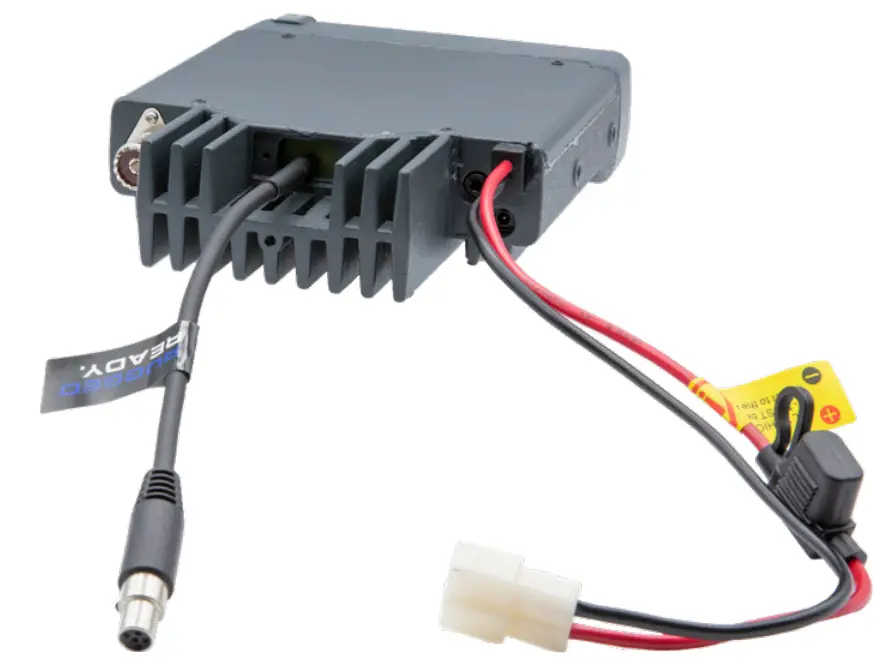
ACCESSORY CONNECTIONS
EXTERNAL SPEAKERS
If you plan to use an external speaker, choose a speaker with an impedance of 8. The external speaker jack accepts a 3.5mm mono (2-conductor) plug. When an external speaker is connected, the radios internal speaker is automatically disabled.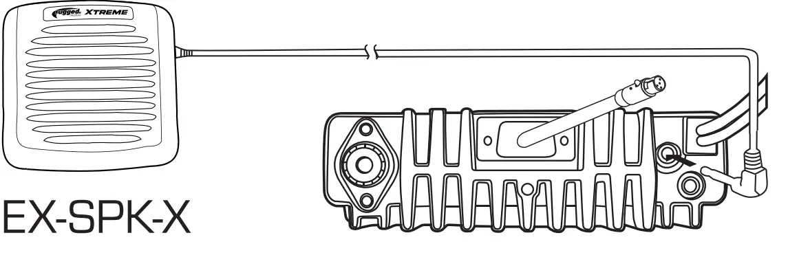
GETTING ACQUAINTED
FRONT PANEL OPERATION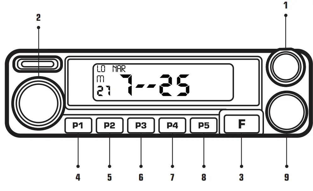
| NO. | Key | Function | |
| 1 | VOLUME | Powers radio on/off and adjusts volume levels. | |
| 2 | Main Dial | Change channels. | |
| 3 | FUNCTION | Press [F] to toggle the function button. | |
| 4 | P1/SCAN | Long press [P1 ]to | scan through radio channels. |
| 5 | P2/MONITOR | Press [P2] to adjust the radio to “0” squelch mode allowing you to receive weaker transmissions. | |
| 6 | P3/SQL | Press [P3] to adjust the squelch. | |
| 7 | P4/BATTERY | Press [P4] to display the number of volts the unit is receiving. | |
| 8 | P5/LOCK | Long press [P5] to lock and unlock the radio. | |
| 9 | Mic Port | Microphone connection port. | |
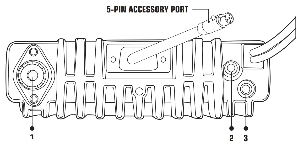
GETTING ACQUAINTED
REAR PANEL OPERATION
No. | Port | Function |
| 1 | Antenna Connector | Connection for 50Ω antenna. |
| 2 | Ext. Speaker Terminal | Terminal for optional external speaker.. |
| 3 | Ext. Power Jack | For manufacturing use only. |
GETTING ACQUAINTED
DISPLAY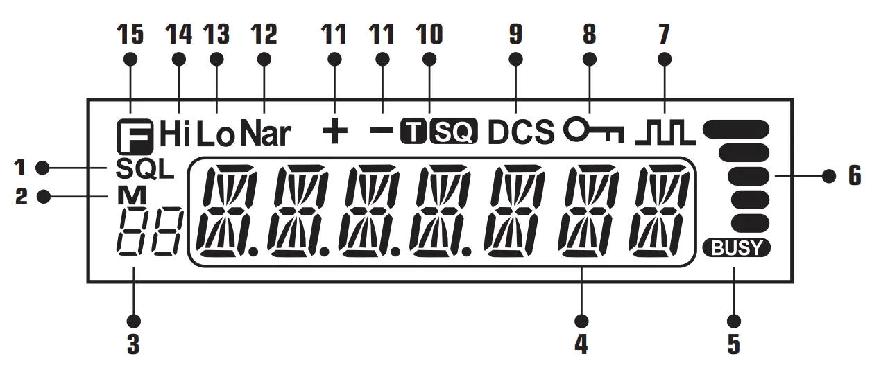
No. | Key | Function |
| 1 | SQL | Squelch level. |
| 2 | M | In channel mode. |
| 3 | Indicates the channel number in channel mode. | |
| 4 | Indicates the frequency or memory name. | |
| 5 | The signal is being received or monitor. | |
| 6 | Signal strength of receiving and transmitting. | |
| 7 | Compander. | |
| 8 | Keypad lock. | |
| 9 |
| Set DCS function. |
| 10 |
| Set CTCSS function. |
| 11 | ÷ — | Offset frequency direction. |
12 | Nar | Narrow band. |
| 13 | LO | Low power. |
| 14 | Hi | High Power |
| 15 | Pressing key. |
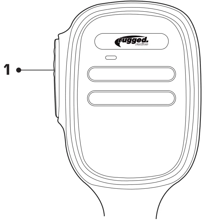
GETTING ACQUAINTED
MICROPHONE
| No. | Icon | Function |
| 1 | PTT | Hold the microphone approximately 4 inches from your mouth, press the key [#1], and speak into the microphone. |
ADDITIONAL FEATURES
Feature | Function |
| Channel Scan | In channel mode, this function is designed to monitor signals in every channel. 1. In channel mode, press the P3 key for 1s to enter into the channel scan |
| Back Light Color | 1. Short press [F] then [P4] to enter the color selection menu. 2. Turn the selector knob to select the desired light color, total 3 colors for choice. 3. Press the [P5] key to confirm and exit. |
| Compander* | Compander function will decrease the background noise and enhance audio clarity, especially in long-range communication. |
*Enabled via software available from RT Systems. 20
TROUBLESHOOTING
| Problem | Possible Cause and Potential Solutions |
| (a) Power is on, nothing appears on Display. | + and – polarities of power connection are reversed. Connect red lead to plus terminal and black lead to minus terminal of DC power supply. |
| (b) Fuse is blown. | Check and solve problems resulting in the blown fuse and replace the fuse with a new fuse. |
| (c) No sound comes from the speaker | Squelch is muted. Decrease squelch level. Tone or CTCSS/DCS squelch is active. |
| (d) Key and Dial do not function. | The key-lock function is activated. Cancel the Key-lock function. |
For additional help call our Tech Department at (888) 541-7223.
We are here to help! HOURS OF OPERATION: Monday – Friday: 8:00 AM – 5:00 PM PST
TONE CODES
CHANGING TONE CODES
Press [F] + [P5] to get to the desired tone type: “T”, “T SQ”, “DCS”, or “SQ DCS”. “T” and “DCS” transmit side only. “T SQ” and “SQ DCS” are transmitted and receive. Use the channel knob to change tone codes. Press [P5] to save. Unless needed, use codes with “SQ” in them. Our tone codes use the same chart and numbering system as listed in GMRS charts. To remove all tone codes on a channel, press [F] + [P5], five times starting from the channel display. To toggle between numbered tone codes [EX: 22] and actual tone codes [EX:141.3], press [P1] when in the tone code menu.*
*Only radios produced after March 1, 2022 (signified by a waterproof power connector) are equipped with this feature. 22
GMRS TONE CODES
CTCSS Analog Tone Codes
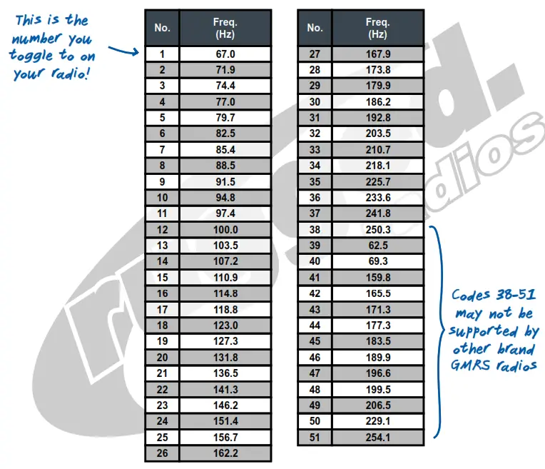
To toggle between numbered tone codes [EX: 22] and actual tone codes [EX:141.3], press [P1] when in the tone code menu. Only radios produced after March 1, 2022 (signified by a waterproof power connector) are equipped with this feature.
VISIT RUGGEDRADIOS.COM
TO LEARN MORE ABOUT OUR INDUSTRY-LEADING GMRS RADIOS
GMRS TONE CODES V
VERSION 1.0.0
NOVEMBER 2021
GMRS TONE CODES
DCS Digital Tone Codes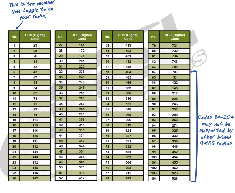
To toggle between numbered tone codes [EX: 22] and actual tone codes [EX:141.3], press [P1] when in tone code menu.
Only radios produced after March 1, 2022 (signified by a waterproof power connector) are equipped with this feature.
VISIT RUGGEDRADIOS.COM TO LEARN MORE
2ABOUT OUR INDUSTRY-LEADING GMRS RADIOS
GMRS TONE CODES
VERSION 1.0.0 | NOVEMBER 2021
| Channel | Frequency (MHz) |
| 1 | 462.5625 |
| 2 | 462.5875 |
| 3 | 462.6125 |
| 4 | 462.6375 |
| 5 | 462.6625 |
| 6 | 462.6875 |
| 7 | 462.7125 |
| 8 | 467.5625 |
| 9 | 467.5875 |
| 10 | 467.6125 |
| 11 | 467.6375 |
| 12 | 467.6625 |
| 13 | 467.6625 |
| 14 | 467.7125 |
| 15 | 462.5500 |
| 16 | 462.5750 |
| 17 | 462.6000 |
| 18 | 462.6250 |
| 19 | 462.6500 |
| 20 | 462.6750 |
| 21 | 462.7000 |
| 22 | 462.7250 |
GMRS REPEATER CHANNELS
| Channel | Transmit Frequency (MHz) | Receive Frequency (MHz) |
| 15RP | 467.5500 | 462.5500 |
| 16RP | 467.5750 | 462.5750 |
| 17RP | 467.6000 | 462.6000 |
| 18RP | 467.6250 | 462.6250 |
| 19RP | 467.6500 | 462.6500 |
| 20RP | 467.6750 | 462.6750 |
| 21RP | 467.7000 | 462.7000 |
| 22RP | 467.7250 | 462.7250 |
SPECIFICATIONS
GENERAL
| Frequency | GMRS |
| Frequency stability | ±2.5ppm |
| Operating temperature | -20°C ~ +60°C |
| Operating voltage | 13.8V DC |
| Dimension | 145x47x190mm |
RECEIVER
| Wide Band | Narrow Band | |
| Sensitivity | 0.25μV | 0.35μV |
| Intermodulation | ≥65dB | ≥60dB |
| Spurious rejection | ≥70dB | ≥70dB |
| Audio response | +1~-3dB (0.3~3KHz) | +1~-3dB (0.3~2.55KHz) |
| Audio distortion | <5% | <5% |
| FM hum and noise | ≥45dB | ≥40dB |
| Audio power output | > 2W@10% | > 2W@10% |
TRANSMITTER
| Wide Band | Narrow Band | |
| Maximum Output power | 45W | 45W |
| Modulation | 16K Φ F3E | 11K Φ F3E |
| Adjacent Channel Power | ≥70dB | ≥60dB |
| FM modulation | ≥40dB | ≥36dB |
| Spurious Emission | ≥60dB | ≥60dB |
| Audio Response | + 1 ~ -3dB(0.3 ~ 3KHz) | + 1 ~ -3dB(0.3 ~ 2.55KHz) |
| Audio Distortion | ≤ 5% | ≤ 5% |
![]() NOTES…………………………………..
NOTES…………………………………..