


Quickstart
This is a
secure
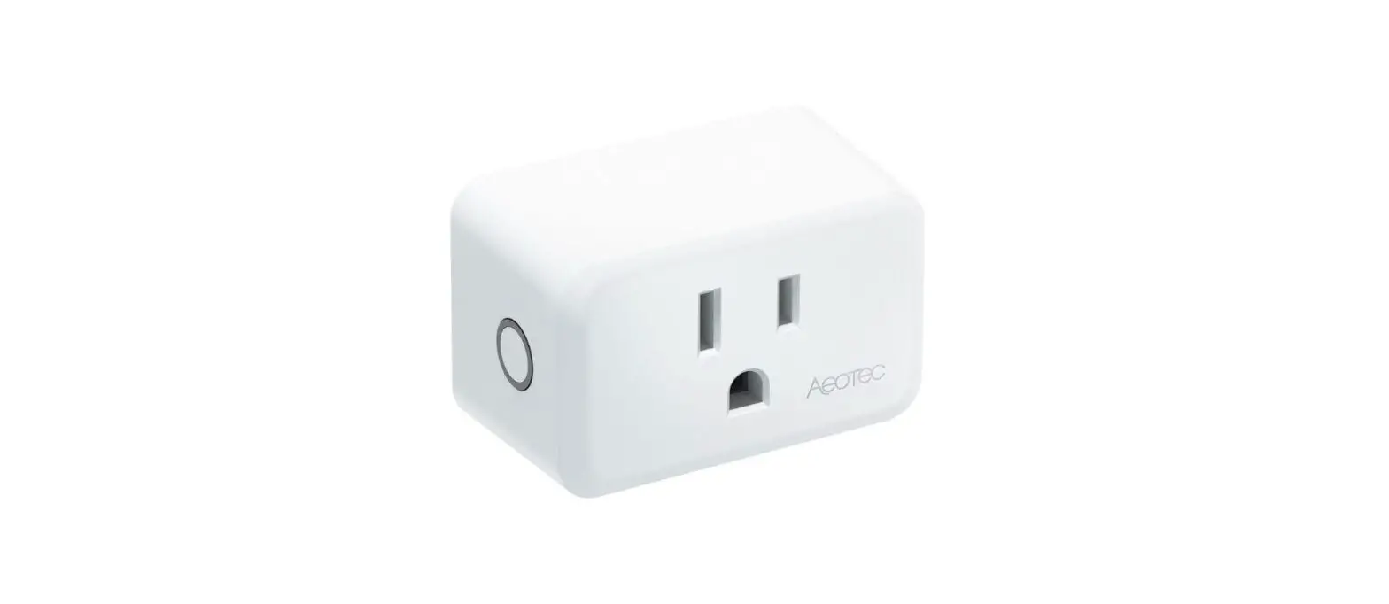
Binary Switch
for
.
To run this device please connect it to your mains power supply.
Important safety information
Please read this manual carefully. Failure to follow the recommendations in this manual may be dangerous or may violate the law.
The manufacturer, importer, distributor and seller shall not be liable for any loss or damage resulting from failure to comply with the instructions in this manual or any other material.
Use this equipment only for its intended purpose. Follow the disposal instructions.
Do not dispose of electronic equipment or batteries in a fire or near open heat sources.
What is Z-Wave?
Z-Wave is the international wireless protocol for communication in the Smart Home. This
device is suited for use in the region mentioned in the Quickstart section.

Z-Wave ensures a reliable communication by reconfirming every message (two-way
communication) and every mains powered node can act as a repeater for other nodes
(meshed network) in case the receiver is not in direct wireless range of the
transmitter.
This device and every other certified Z-Wave device can be used together with any other
certified Z-Wave device regardless of brand and origin as long as both are suited for the
same frequency range.
If a device supports secure communication it will communicate with other devices
secure as long as this device provides the same or a higher level of security.
Otherwise it will automatically turn into a lower level of security to maintain
backward compatibility.
For more information about Z-Wave technology, devices, white papers etc. please refer
to www.z-wave.info.
Product Description
Aeotec Smart Switch 7 is a Z-Wave Switch plug-in module specifically used to enable Z-Wave command and control (on/off) of any plug-in tool. It can report immediate wattage consumption or kWh energy usage over a period of time. In the event of power failure, non-volatile memory retains all programmed information relating to the units operating status.The Plug is also a security S2 Z-Wave device, it supports Over The Air (OTA) feature for the products firmware upgrade and SmartStart network pairing feature.
Prepare for Installation / Reset
Please read the user manual before installing the product.
In order to include (add) a Z-Wave device to a network it must be in factory default
state. Please make sure to reset the device into factory default. You can do this by
performing an Exclusion operation as described below in the manual. Every Z-Wave
controller is able to perform this operation however it is recommended to use the primary
controller of the previous network to make sure the very device is excluded properly
from this network.
Safety Warning for Mains Powered Devices
ATTENTION: only authorized technicians under consideration of the country-specific
installation guidelines/norms may do works with mains power. Prior to the assembly of
the product, the voltage network has to be switched off and ensured against re-switching.
Inclusion/Exclusion
On factory default the device does not belong to any Z-Wave network. The device needs
to be added to an existing wireless network to communicate with the devices of this network.
This process is called Inclusion.
Devices can also be removed from a network. This process is called Exclusion.
Both processes are initiated by the primary controller of the Z-Wave network. This
controller is turned into exclusion respective inclusion mode. Inclusion and Exclusion is
then performed doing a special manual action right on the device.
Quick trouble shooting
Here are a few hints for network installation if things dont work as expected.
- Make sure a device is in factory reset state before including. In doubt exclude before include.
- If inclusion still fails, check if both devices use the same frequency.
- Remove all dead devices from associations. Otherwise you will see severe delays.
- Never use sleeping battery devices without a central controller.
- Dont poll FLIRS devices.
- Make sure to have enough mains powered device to benefit from the meshing
Association – one device controls an other device
Z-Wave devices control other Z-Wave devices. The relationship between one device
controlling another device is called association. In order to control a different
device, the controlling device needs to maintain a list of devices that will receive
controlling commands. These lists are called association groups and they are always
related to certain events (e.g. button pressed, sensor triggers, …). In case
the event happens all devices stored in the respective association group will
receive the same wireless command wireless command, typically a ‘Basic Set’ Command.
Association Groups:
Group NumberMaximum NodesDescription
| 1 | 5 | This is the lifeline group.Device Reset Locally:When factory reset.Notification Report (Type=0x08, Event=0x08):When over load detected.Basic Report:When switch state changed. See parameter 42for more information.Switch Binary Report:When switch state changed. See parameter 42for more information.Switch Multilevel Report:Issued when multilevel switch value of theindicator light has changed.Switch Color Report:Issued when a color component level of theindicator has changed.Meter Report:Issued periodically according to the parameter23,24,25,26 or above the threshold.Clock Report:Issued per hour.Indicator Report:Issued when the indicator light changed. |
| 2 | 5 | Mirror of endpoint 1. |
| 3 | 5 | Trigger to send Scene Activation Set to this group when the load wattage above the parameter 6’s setting. |
Configuration Parameters
Z-Wave products are supposed to work out of the box after inclusion, however
certain configuration can adapt the function better to user needs or unlock further
enhanced features.
IMPORTANT: Controllers may only allow configuring
signed values. In order to set values in the range 128 … 255 the value sent in
the application shall be the desired value minus 256. For example: To set a
parameter to 200 it may be needed to set a value of 200 minus 256 = minus 56.
In case of a two byte value the same logic applies: Values greater than 32768 may
needed to be given as negative values too.
Parameter 1: LED Setting
This parameter is used to change the reaction of LED setting.0 – Disable LED completely. LED will only be used for network operation indicator, such as inclusion, exclusion, factory reset.
Size: 1 Byte, Default Value: 2
SettingDescription
| 0 | Disable LED completely |
| 1 – 0 | Turn on between particular times only (act as night light). |
| 2 – 0 | Display On/Off Status. |
Parameter 10: Over-load Protection
Turn off switch when current of load connected bypasses the maximum allowed power regardless of always on setting. Unit W.0 – disable overload protection 1~1800 – When watt detected above this setting value, the switch will be turned off immediately. And an over-load notification will be sent.
Size: 2 Byte, Default Value: 1800
SettingDescription
| 0 | disable overload protection |
| 1 – 1800 | When watt detected above this setting value, the switch will be turned off immediately. And an over-load notification will be sent. |
Parameter 11: Over-voltage Protection
This parameter is used to set the over-voltage protect value, unit V.0 – disable over-voltage protection 95~255 – When voltage detected above this setting value, the switch will be turned off immediately. And an over-voltage notification will be sent.
Size: 1 Byte, Default Value: 135
SettingDescription
| 0 | disable over-voltage protection |
| 1 – 255 | When voltage detected above this setting value, the switch will be turned off immediately. And an over-voltage notification will be sent. |
Parameter 19: Threshold Check Time
Set the period of threshold check. Unit second.0 – disable all threshold settings 1~255 – set in seconds on how fast device checks for threshold settings
Size: 1 Byte, Default Value: 5
SettingDescription
| 0 | disable all threshold settings |
| 1 – 255 | set in seconds on how fast device checks for threshold settings |
Parameter 2: Night Light On Time
This parameter is used to configure the Night Light on time. User can use Color CC to change the Night Light color(default Red). Only useful when parameter 1 is set to 1.RR = ReservedHH = HoursMM = MinutesSS = SecondsDefault = 0x00180000 means 6pm
Size: 4 Byte, Default Value: 1572864
SettingDescription
| 0 – 2316633 | This parameter is used to configure the Night Light on time.RR = Reserved HH = Hours MM = Minutes SS = Seconds Default = 0x00180000 means 6pm |
Parameter 20: kWh Report Threshold
Energy kWh threshold reporting enable/disable. Unit kWh.
Size: 2 Byte, Default Value: 100
SettingDescription
| 0 | Disable kWh threshold reporting |
| 1 – 10000 | kWh threshold setting. |
Parameter 21: Watt Report Threshold
Threshold setting for Watt for inducing automatic report.Unit W.
Size: 2 Byte, Default Value: 0
SettingDescription
| 0 | Disable Watt threshold reporting |
| 1 – 2500 | Watt threshold setting. |
Parameter 22: Current Report Threshold
Threshold settings for current for inducing automatic report. Unit A
Size: 1 Byte, Default Value: 0
SettingDescription
| 0 | Disable Watt threshold reporting |
| 1 – 150 | Current threshold setting. |
Parameter 23: Watt Automatic Report Time
Set the automatic report time of Watt. Unit second.
Size: 2 Byte, Default Value: 600
SettingDescription
| 0 – 65535 | Set the automatic report time of Watt |
Parameter 24: kWh Automatic Report Time
Set the automatic report time of kWh. Unit second.
Size: 2 Byte, Default Value: 600
SettingDescription
| 0 – 65535 | Set the automatic report time of kWh. Unit second. |
Parameter 25: Voltage Automatic Report Time
Set the automatic report time of Voltage. Unit second.
Size: 2 Byte, Default Value: 600
SettingDescription
| 0 – 65535 | Set the automatic report time of Voltage. Unit second. |
Parameter 255: Factory Reset or Initialization
Restore the product to factory settings and remove from the network.0x55555555 – Restore the product to factory settings and remove from the network. Other – Initialize all configuration parameters to default values.
Size: 4 Byte, Default Value: 0
SettingDescription
| 0 | Initialize all configuration parameters to default values. |
| 4294967295 | Restore the product to factory settings and remove from the network |
Parameter 26: Current Automatic Report Time
Set the automatic report time of Current. Unit second.
Size: 2 Byte, Default Value: 600
SettingDescription
| 0 – 65535 | Set the automatic report time of Current. Unit second. |
Parameter 3: Night Light Off Time
This parameter is used to configure the Night Light off time. Only useful when parameter 1 is set to 1.RR = ReservedHH = HoursMM = MinutesSS = SecondsDefault = 0x00060000 means 6am
Size: 4 Byte, Default Value: 393216
SettingDescription
| 0 – 2316633 | This parameter is used to configure the Night Light off time. Only useful when parameter 1 is set to 1. RR = Reserved HH = Hours MM = Minutes SS = Seconds Default = 0x00060000 means 6am |
Parameter 30: Alarm Settings
Determines if alarms are enabled in Switch, and what Switch will react to which alarms.
Size: 1 Byte, Default Value: 0
SettingDescription
| 1 – 0 | Smoke Alarm |
| 2 – 0 | CO Alarm |
| 4 – 0 | CO2 Alarm |
| 8 – 0 | Heat Alarm |
| 16 – 0 | Water Alarm |
| 32 – 0 | Access Control |
| 64 – 0 | Home Security |
| 128 – 0 | Motion Sensor trigger |
| 0 | Disable alarm |
Parameter 31: Alarm Response
Enabled by Alarm Settings, and determines what the switch does in the case an alarm is triggered.0 – disable , no reaction to alarm settings 1 – Switch is ON 2 – Switch is OFF 3~255 – Sets rate at which Switch turns ON and OFF in seconds. (i.e. If set to 3, then Switch will turn ON in 0.3 seconds, and then turn OFF in 0.3 seconds in a cycle until user disables the alarm manually. If set to 255, then it will cycle every 25.5 seconds)
Size: 1 Byte, Default Value: 0
SettingDescription
| 0 | disable , no reaction to alarm settings |
| 1 | Switch is ON |
| 2 | Switch is OF |
| 3 – 255 | Sets rate at which Switch turns ON and OFF in seconds. |
Parameter 32: Alarm Disable Setting
Determines the method of disabling the alarm of the device.0 – Can be disabled by 1 tapping Switches action button once. 1 – Can be disabled by 2 tapping Switches action button within 1 second. 2 – Can be disabled by 4 tapping Switches action button within 2 seconds. 4 – Can be disabled by pressing and holding Switches action button about 4 seconds. 5~255 – Sets the duration of the alarm in seconds (i.e Sets this setting to 50, the alarm state of the switch will disable after 50 seconds)
Size: 1 Byte, Default Value: 1
SettingDescription
| 0 | Can be disabled by 1 tapping Switches action button once. |
| 1 | Can be disabled by 2 tapping Switches action button within 1 second. |
| 2 | Can be disabled by 4 tapping Switches action button within 2 seconds. |
| 4 | Can be disabled by pressing and holding Switches action button about 4 seconds. |
| 5 – 255 | Sets the duration of the alarm in seconds (i.e Sets this setting to 50, the alarm state of the switch will disable after 50 seconds) |
Parameter 4: LED Blink Duration
Set the duration of blink, unit second.0 – indicates that it is not blinking1~255 – set the duration
Size: 1 Byte, Default Value: 0
SettingDescription
| 0 | Indicates that it is not blinking |
| 1 – 255 | Set the duration |
Parameter 40: Automatic Off Timer
Acts as auto off after as soon as the switch turns ON, setting is set in seconds.0 – no auto off with timer 1~86400 – seconds
Size: 4 Byte, Default Value: 0
SettingDescription
| 0 | no auto off with timer |
| 1 – 86400 | seconds |
Parameter 41: Automatic On Timer
Acts as auto on after as soon as the switch turns OFF, setting is set in seconds.0 – no auto on with timer 1~86400 – seconds
Size: 4 Byte, Default Value: 0
SettingDescription
| 0 | no auto on with timer |
| 1 – 86400 | Seconds |
Parameter 42: Report Command Setting
Which report will be sent to lifeline group when the output state is changed.0 – Send nothing 1 – Send Basic Report 2 – Send Switch Binary Report
Size: 1 Byte, Default Value: 2
SettingDescription
| 0 | Send nothing |
| 1 – 0 | Send Basic Report |
| 2 – 0 | Send Switch Binary Report |
Parameter 5: LED Blink Speed
Set amount of blinks per second.i.e. If set to 5, it should blink 5 times per second.
Size: 1 Byte, Default Value: 5
SettingDescription
| 1 – 24 | Set amount of blinks per second. |
Parameter 6: Send Alert When In Use
Send alert when in use. A Scene Activation Set command will be sent when energy draw is above this setting value.0 – disable1~3000 – enable, unit W
Size: 2 Byte, Default Value: 100
SettingDescription
| 0 | Disable |
| 1 – 3000 | Enable |
Parameter 7: Plug Always On
Prevents the plug from being turned off via its button.0 – the plug will operate as normal and can be turned on or off. 1 – the button on the plug will be disabled for on and off commands, but still work for network inclusion and exclusion. 2 – the plug will ignore any commands to turn it off and it will ignore any use of the button (but still work for network inclusion and exclusion)
Size: 1 Byte, Default Value: 0
SettingDescription
| 0 | the plug will operate as normal and can be turned on or off. |
| 1 – 0 | the button on the plug will be disabled for on and off commands, but still work for network inclusion and exclusion. |
| 2 – 0 | the plug will ignore any commands to turn it off and it will ignore any use of the button (but still work for network inclusion and exclusion) |
Parameter 8: Power Out Action
Set the plugs action in case of power out.0 – last status1 – power on2 – power off
Size: 1 Byte, Default Value: 0
SettingDescription
| 0 | Last status |
| 1 | Power On |
| 2 | Power Off |
Parameter 9: Group3 Scene Id
Set the scene id when Scene Activation Set Command sent through group3. Refer parameter 6 for more information.
Size: 1 Byte, Default Value: 255
SettingDescription
| 1 – 255 | Set the scene id when Scene Activation Set Command sent through group3. |
Technical Data
| Hardware Platform | ZGM130 |
| Device Type | Binary Switch |
| Network Operation | Always On Slave |
| Firmware Version | HW: 1 FW: 1.02 |
| Z-Wave Version | 7.12.2 |
| Certification ID | ZC12-20050064 |
| Z-Wave Product Id | 0x0371.0x0103.0x0017 |
| Security V2 | S2_UNAUTHENTICATED ,S2_AUTHENTICATED |
| Frequency | XXfrequency |
| Maximum transmission power | XXantenna |
Supported Command Classes
- Application Status
- Association Grp Info V3
- Association V2
- Basic V2
- Clock
- Configuration V4
- Device Reset Locally
- Firmware Update Md V5
- Indicator V3
- Manufacturer Specific V2
- Meter V5
- Multi Channel Association V3
- Multi Channel V4
- Notification V8
- Powerlevel
- Scene Activation
- Scene Actuator Conf
- Security
- Security 2
- Supervision
- Switch Binary V2
- Switch Color V3
- Switch Multilevel V4
- Transport Service V2
- Version V3
- Zwaveplus Info V2
Explanation of Z-Wave specific terms
- Controller — is a Z-Wave device with capabilities to manage the network.
Controllers are typically Gateways,Remote Controls or battery operated wall controllers. - Slave — is a Z-Wave device without capabilities to manage the network.
Slaves can be sensors, actuators and even remote controls. - Primary Controller — is the central organizer of the network. It must be
a controller. There can be only one primary controller in a Z-Wave network. - Inclusion — is the process of adding new Z-Wave devices into a network.
- Exclusion — is the process of removing Z-Wave devices from the network.
- Association — is a control relationship between a controlling device and
a controlled device. - Wakeup Notification — is a special wireless message issued by a Z-Wave
device to announces that is able to communicate. - Node Information Frame — is a special wireless message issued by a
Z-Wave device to announce its capabilities and functions.


