LCI Level-Up Towable System
System and Safety Information
- Be sure to park the unit on solid, level ground.
- Ensure all jack landing locations are cleared of debris and obstructions and also free of depressions.
- When parking the unit on extremely soft surfaces, utilize load distribution pads under each jack.
- People and pets should be clear of unit while operating leveling system.
- Be sure to keep hands and other body parts clear of fluid leaks. Oil leaks in the Lippert Leveling
System may be under high pressure and can cause serious skin-penetrating injuries.
WARNING: Lippert Components Inc. recommends that a trained professional be employed to change the tires on the unit. Ensure that the unit is properly supported with jack stands, or other adequate devices, under the frame of the unit prior to commencing any service or repair procedure. Any attempts to change the tires or perform other service while unit is supported solely by the LCI Level-Up® with Automatic Leveling System could result in death, serious injury, unit or property damage.
Introduction
Level-Up® is an Automatic Leveling system. This system is equipped with 14K aluminum landing gear and 8K aluminum leveling jacks. The jacks in the Level-Up® system work in pairs.
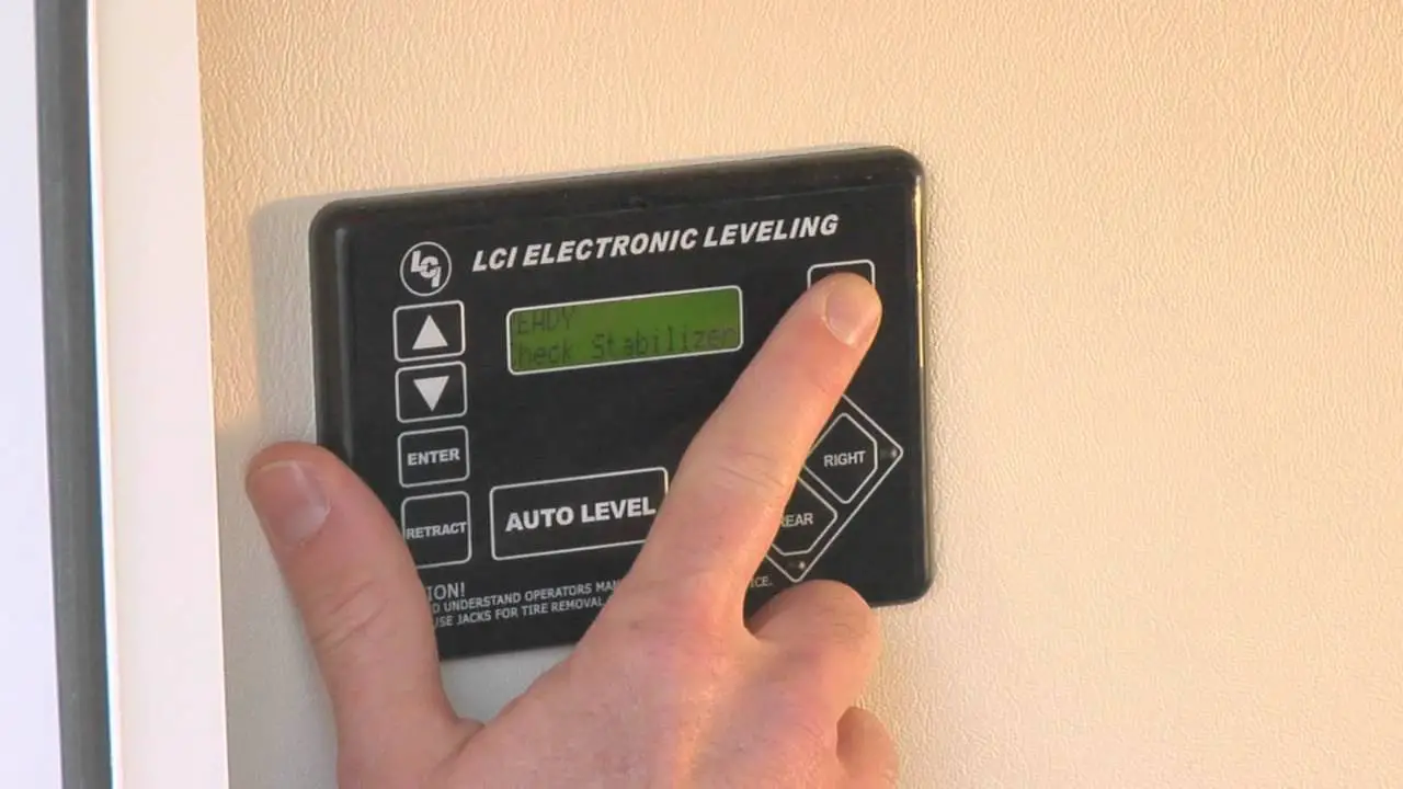
Touch Pad Diagram
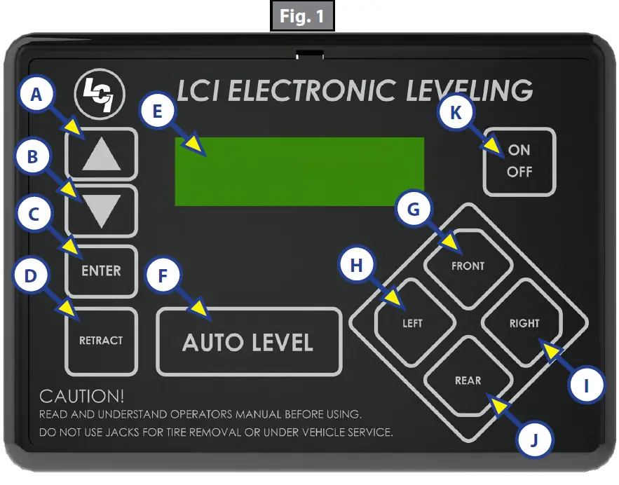
| Callout | Description |
| A | Up Arrow – Scrolls up through the menu on LCD. |
| B | Down Arrow – Scrolls down through the menu on LCD. |
| C | Enter – Activates modes and procedures indicated on LCD. |
| D | Retract – Places leveling system into retract mode – Manual mode ONLY. |
| E | LCD Display – Displays procedures and results. |
| F | Auto Level – Places leveling system into auto level mode. |
| G | Front Button – Activates both front jacks. |
| H | Left Button – Activates left leveling jack(s) in manual mode. |
| I | Right Button – Activates right leveling jack(s) in manual mode. |
| J | Rear Button – Activates leveling jacks in manual mode. |
| K | Power Button – Turns leveling system on and off. |
Prior to Operation
The leveling system shall only be operated under the following conditions:
- The unit is parked on a reasonably level surface.
- Be sure all persons, pets and property are clear of the unit while LCI Level-Up Automatic System is in operation.
- Ensure the battery of the unit is fully charged or that the unit is plugged into shore power prior to attempting to operate the system. Level-Up requires a minimum of 12V DC from the battery for proper operation.
Operation
Basic Jack Operation
- Landing gear Jacks
Landing gear jacks can be operated any time the system is “ON” but NOT in the “AUTO MODE.” By pushing the “FRONT” button (Fig. 1G), both front or landing gear jacks can be extended. If the touch pad is put in the “RETRACT” mode, indicated by the orange illuminated LED next to the “RETRACT” button (Fig. 1D), the front jacks can be retracted together by pushing the “FRONT” button. - Level-Up jacks
The Level-Up jacks operate when the “AUTO MODE” is activated or the touch pad is in the “MANUAL MODE.” Once system is in “MANUAL MODE,” pressing the “REAR” button (Fig. 1J) will extend all Level-Up jacks at the same time. Press the “LEFT” or “RIGHT” buttons (Fig. 1H and 1I) to operate Level-Up jacks on the left or right side of the unit, respectively.
5th Wheel Operation
Unhitching Instructions
- Push touch panel “ON/OFF,” (Fig. 1K) to turn system on. LCD Screen (Fig. 1E) lights up.
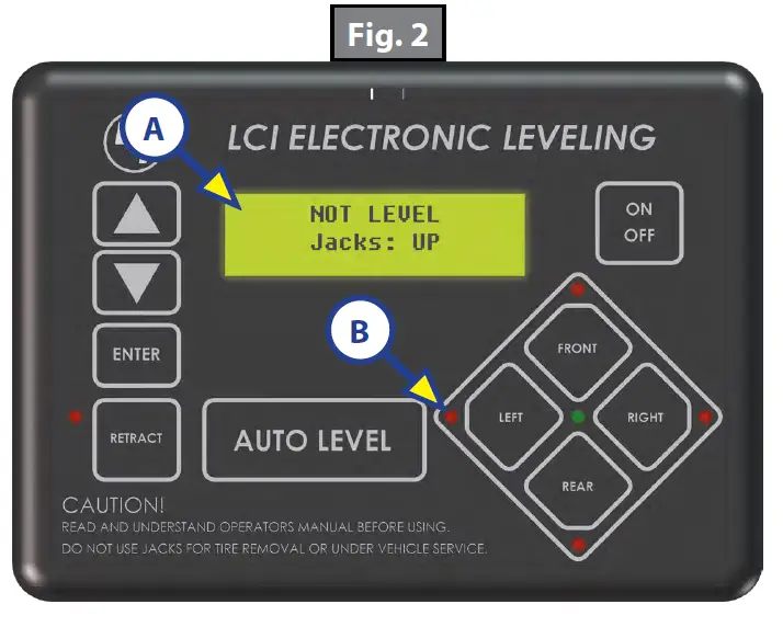
- LCD will display status … “NOT LEVEL JACKS: UP” (Fig. 2A).
NOTE: Orange arrow lights (Fig. 2B) may come on, indicating the current disposition of the unit. - Push “FRONT” button (Fig. 1G) to extend landing gear jacks and lift front of unit to take the weight of the 5th wheel off of the hitch.
- Uncouple the 5th wheel connection on the tow vehicle.
- Pull tow vehicle away and park at a safe distance.
Auto Level
NOTE: Prior to unhitching from the tow vehicle, ensure unit is parked on a level surface and chock the tires of the unit.
1. After unhitching from tow vehicle press “AUTO LEVEL” (Fig. 1F).
NOTE: Pressing any button during an Auto Level sequence will abort the auto leveling cycle.
NOTE: In order for hitch recognition feature to function, the auto level sequence MUST be started with the front of the unit above level.
Auto Level Sequence
- Front landing gear retract, lowering the front of the unit below level, stopping, then lifting the front end to level the unit front to back.
- The left side leveling jack(s) extend and raise the roadside of the unit.
- The right side leveling jack(s) extend and raise the curbside of the unit, beginning side to side leveling.
- The front landing gear extend to complete the leveling cycle.
NOTE: Additional left to right or front to back leveling may occur if the controller deems necessary.
NOTE: If the auto level sequence does not happen as stated above, check to ensure proper manual function in all zones.
Hitch Recognition
- Turn on touch pad.
- Press the “LEFT” and “RIGHT” buttons simultaneously (Fig. 1H and 1I).
- The front of the unit will raise to the height where the auto level sequence was started.
NOTE: If the auto level sequence was started with the front of the unit in a below level condition, the Hitch Recognition will not function and the LCD will display “Feature Disabled.” In order for the hitch recognition feature to function, the auto level sequence MUST be started with the front of the unit above level. - Connect tow vehicle and make sure 5th wheel and hitch are connected and locked.
- Push “UP” arrow (Fig. 1A) until ”AUTO RETRACT” appears in LCD screen.
- Push “ENTER” (Fig. 1C). System will immediately retract all jacks.
Travel Trailer Operation
Unhitching Instructions
NOTE: Prior to unhitching from the tow vehicle, ensure unit is parked on a level surface and chock the tires of the unit.
- Push “ON/OFF” button (Fig. 1K) to turn system “ON” (green light).
- Push “UP” (Fig. 1A) or “DOWN” arrow (Fig. 1B) to scroll through features to “MANUAL MODE” in display.
- Push “ENTER” (Fig. 1C).
- Push “FRONT” button (Fig. 1G) to extend front jacks to the ground until the trailer is unhitched from the tow vehicle.
NOTE: The Power Tongue Jack should ONLY be used when storing the trailer.
Auto Level
NOTE: The Power Tongue Jack MUST be retracted prior to starting auto level sequence (Fig. 3 shows the LCD alert).
After unhitching from tow vehicle press “AUTO LEVEL” (Fig. 1F)
NOTE: Pressing any button during an Auto Level sequence will abort the auto leveling cycle.
NOTE: In order for hitch recognition feature to function, the auto level sequence MUST be started with the front of the unit above level.
Auto Level Sequence
- Front jacks retract, lowering the front of the unit below level, stopping, then lifting the front end to level the unit front to back.
- The rear left side leveling jack extends and raises the roadside of the unit.
- The rear right side leveling jack extends and raises the curbside of the unit, beginning side to side leveling.
- The front jacks extend to complete the leveling cycle.
NOTE: Additional left to right or front to back leveling may occur if the controller deems necessary.
NOTE: If the auto level sequence does not happen as stated above, check to ensure proper manual function in all zones.
Hitch Recognition
- Turn on touch pad.
- Press the left and right buttons simultaneously (Fig. 1H and 1I).
- The front of the unit will raise to the height where the auto level sequence was started.
NOTE: If the auto level sequence was started with the front of the unit in a below level condition, the Hitch Recognition will not function and the LCD will display “Feature Disabled.” In order for hitch recognition feature to function, the auto level sequence MUST be started with the front of the unit above level. - Connect tow vehicle and make sure travel trailer and hitch are connected and locked.
- Push “UP” arrow until ”AUTO RETRACT” appears in LCD screen.
- Push “ENTER.” System will immediately retract all jacks.
Manual Operation
Front landing gear (5th Wheels) or Front jacks (Travel Trailers)
NOTE: The landing gear or front jacks will operate manually any time system is “ON” except in “AUTO MODE”
A. Push “ON/OFF” (Fig. 1K) to turn system on.
B. Push “UP” arrow (Fig. 1A) once or until screen reads “MANUAL MODE” (Fig. 4).
C. Push “ENTER” (Fig. 1C) once while screen reads “MANUAL MODE” (Fig. 4).
D. Push “FRONT” (Fig. 1G) to extend front landing gear or front jacks.
E. Push “RETRACT” (Fig. 1D) and orange LED (Fig. 5) comes on.
F. Push “FRONT” (Fig. 1G) to retract front landing gear or front jacks.
NOTE: If orange LED (Fig. 5) is on, landing gear or jacks will retract. If orange LED (Fig. 5) is off, landing gear or jacks will extend.
G. Push “ON/OFF” to turn system off.
H. After 3 minutes system will turn off by itself.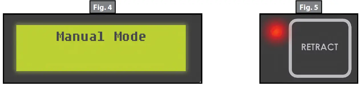
Level-Up jacks – EXTEND
A. Turn “ON/OFF” button “ON.”
B. Push scroll arrow to display “MANUAL MODE” (Fig. 4).
C. Push “ENTER” button, “MANUAL MODE” displayed (Fig. 4).
NOTE: By pushing “RIGHT,” passenger side Level-Up jacks operate. By pushing “LEFT,” driver side Level-Up jacks operate, and so on.
Level-Up jacks – RETRACT
A. Push “RETRACT” and orange LED (Fig. 5) will come on.
B. Push “REAR” to retract all Level-Up jacks.
C. To extend, the “RETRACT“ light (Fig. 5) should be off.
NOTE: The side to side movement in manual mode is limited to 5o of tilt.
Zero Point Calibration
The “Zero Point” is the programmed point that the unit will return to each time the Auto Level feature is used. The “Zero Point” must be programmed prior to using the Auto Level feature to ensure the proper operation of the system.
NOTE: Prior to starting this procedure, double check all connections on the controller, jacks, and touch pad.
- Manually run the jacks to level the unit. This is best achieved by placing a level in the center of the unit and leveling it both front to back and then side to side. (See “Basic Jack Operation” for instructions on how to manually operate the system).
- Once the unit is level, turn off the touch pad.
- With the touch pad off, press and release the “FRONT” button (Fig. 1G) ten (10) times and then press and release the “REAR” button (Fig. 1J) ten (10) times.
- The touch pad will flash and beep and the display will read “ZERO POINT CALIBRATION ENTER to set, Power to Exit” (Fig. 5).
- To set the current position as the zero point, press the “ENTER” button (Fig. 1C).

- LCD display will read “Zero Point stability check” (Fig. 6).

- LCD display will read “Zero point set successfully” once process is complete (Fig. 7).

- The system will set this point as its level state and the touch pad will turn off.


Maintenance
- Each month, check that the fluid level is within 1/4″ of the fill spout lip while jacks and slide-outs are fully retracted.
NOTE: Always fill the reservoir with the jacks and slide-outs in the fully retracted position. Filling reservoir when jacks and slide-outs are extended will cause reservoir to overflow into its compartment when jacks and slide-outs are retracted. - Inspect and clean all power unit electrical connections prior to the first use of the unit of the season and prior to storing the unit. If corrosion is evident, clean all corrosion with a wire brush and apply dielectric grease to the connections.
- Remove dirt and road debris from jacks as needed.
- If jacks are down for extended periods, it is recommended to spray exposed leveling jack rods with a silicone lubricant every three months for protection. If the unit is located in a salty air environment, it is recommended to spray the rods every 4 to 6 weeks.
Fluid Recommendation
The Lippert Electronic Leveling System is pre-filled, primed and ready to operate direct from the manufacturer. Type “A” Automatic Transmission Fluid (ATF) is utilized and will work. ATF with Dexron III® or Mercon 5® or a blend of both is recommended by Lippert Components, Inc.
In colder temperatures (less than 10° F) the jacks may extend and retract slowly due to the fluid’s molecular nature. For cold weather operation, fluid specially formulated for low temperatures may be desirable. For a list of approved fluid specifications, see TI-188.
Troubleshooting
Error Display in LCD Screen
NOTE: To clear Error Code, push “ENTER” – If error remains, the code will appear again.
| LCD Message | What’s Happening? | What Should I Do? |
| “EXCESS ANGLE” | Unsecured controller. Uneven or sloped site. | Check and secure controller placement. Relocate the unit. |
| “BAD CALIBRATION” | Unit zero point was not set correctly. | Reset zero point. See “Calibration.” |
| “FEATURE DISABLED” | Front of unit below level when starting Auto Level process. | Raise front of unit above level and restart Auto Level process. |
| “LOW VOLTAGE” | Bad connection or wiring. Discharged or bad battery. | Check wiring – repair or replace. Test battery voltage under load – charge or replace. |
| “OUT OF STROKE” | Unsecured controller. Uneven or sloped site. | Check and secure controller placement. Relocate the unit. |
| “EXTERNAL SENSOR” | Bad connection or wiring. | Replace or repair connection to rear remote sensor. |
| “JACK TIME OUT” | System could not level in expected time. | Check for obstructions, leaks, fluid level and voltage to power unit motor under load. |
| “AUTO LEVEL FAILURE” | Unsecured controller. Voltage drop. | Check and secure controller placement. Test battery voltage under load – charge or replace. |
Manual Override
The LCI Level-Up Automatic Leveling System can be manually operated with an electric drill. In the event of electrical or system failure, this manual method of extending and retracting the jacks can be used. See the instructions below.
NOTE: Unhook the power unit motor from the power source prior to attempting the manual override procedure.
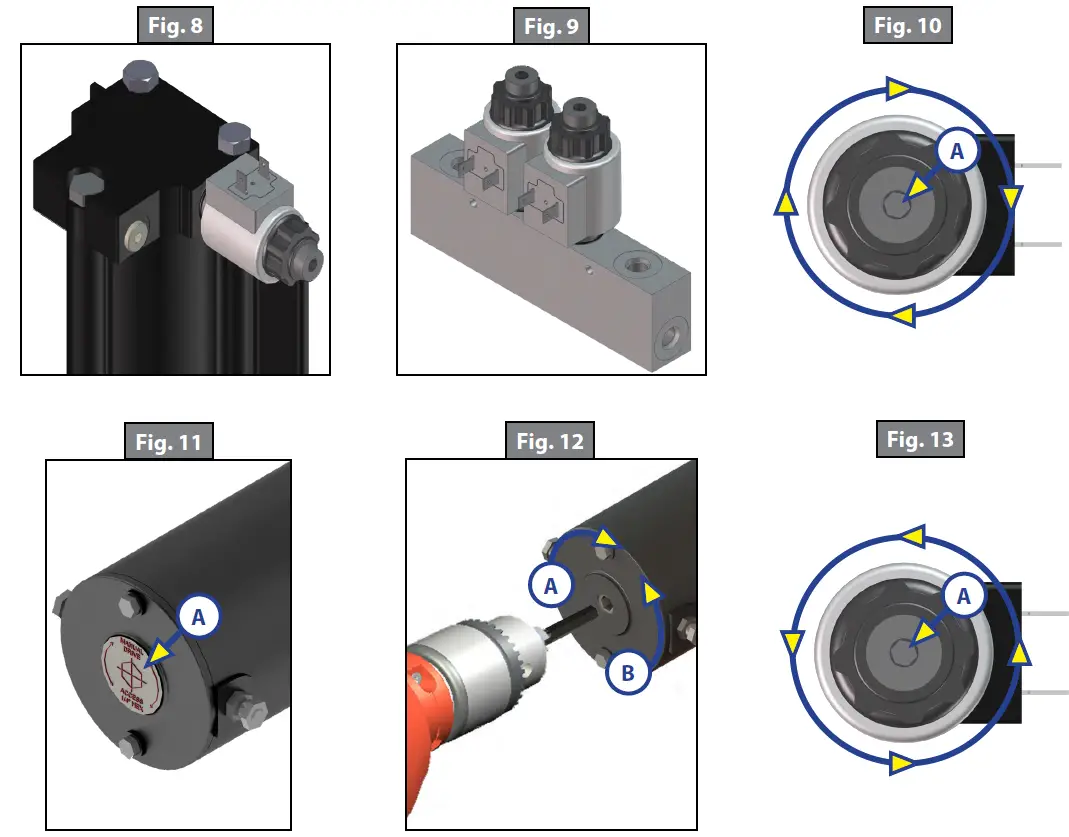
- Locate the valves that are paired with the landing gear or leveling jack to be manually overridden.
A. Landing Gear – Valve located on the landing gear (Fig. 8).
B. Leveling Jacks – Valve located on manifold (Fig. 9). - Using a 5/32” hex wrench, open the valve by turning the manual override set screw clockwise (Fig. 10A).
- Remove protective label (Fig. 11A) from power unit to reveal the manual override coupler.
- Using an electric drill with a 1/4″ hex bit, insert the hex bit into the manual override coupler to manually operate the Level-Up system (Fig. 12).
A. Run the drill forward (clockwise) to retract the landing gear or leveling jack (Fig. 12A).
B. Run the drill in reverse (counterclockwise) to extend the landing gear or leveling jack (Fig. 12B). - Be sure to turn the manual override set screw on the valve (Fig. 13A) back to the counterclockwise position after extending or retracting the landing gear or leveling jack.

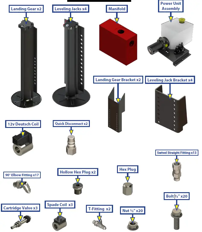
LEVELING AND STABILIZATION
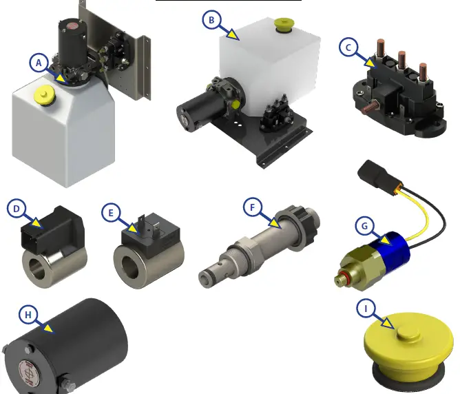
| Callout | Part # | Description |
| A | 251910 | Vertical Power Unit |
| B | 251909 | Horizontal Power Unit |
| C | 118246 | Dual Polarity Solenoid |
| D | 174184 | Deutsch Coil |
| E | 176954 | Spade Coil |
| F | 177094 | Cartridge Valve |
| G | 142927 | Pressure Switch |
| H | 167576 | Power Unit Motor |
| I | 157505 | Fill Cap |
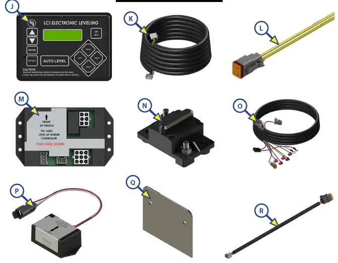
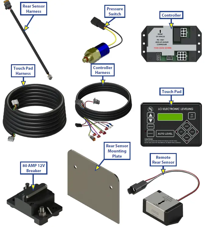
| Callout | Part # | Description |
| J | 234802 | LCD Touch Pad |
| K | 241316 | Touch Pad Harness |
| L | 237855 | Deutsch 2 Wire Pigtail Harness |
| M | 241129 | Controller |
| N | *135461 | 80 AMP 12V Breaker |
| O | 241318 | Controller Harness |
| P | 232201 | Rear Sensor |
| Q | 231775 | Rear Sensor Mounting Plate |
| R | 241314 | Rear Sensor Harness |
| NOTE: * Circuit Protection requirement is 50 amps to 100 amps as needed by RVIA Standards and OEM requirements. | ||
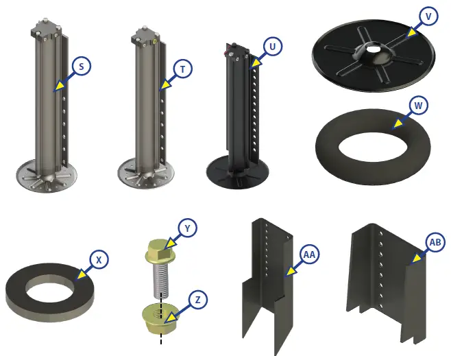
| Callout | Part # | Description |
| S | 257125 | Right 14k lb. Rated Landing Gear, Aluminum |
| T | 257126 | Left 14k lb. Rated Landing Gear, Aluminum |
| U | 195860 | 8k lb. Rated Leveling Jack, Aluminum |
| V | 113309 | Footpad |
| W | 123932 | Footpad O-Ring |
| X | 178208 | Footpad Washer |
| Y | 118076 | Bolt; 1/2″ – 20 |
| Z | 178210 | Nut; 1/2″ – 20 |
| AA | 134989 | Mount Bracket |
| AB | 218210 | Mount Bracket |
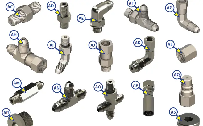
| Callout | Part # | Description |
| AC | 113042 | Hose Union Fitting |
| AD | 113131 | Straight Fitting |
| AE | 113128 | JIC to O-Ring 90 Degree Elbow Fitting |
| AF | 113130 | T-Fitting with O-Ring on Run |
| AG | 113134 | Swivel Elbow Fitting |
| AH | 113135 | Swivel T-Fitting |
| AI | 113129 | 45 Degree Elbow Fitting |
| AJ | 113133 | Swivel Straight Fitting |
| AK | 141020 | Swivel Elbow Fitting |
| AL | 216288 | Steel Cap Fitting |
| AM | 139417 | Long Straight Fitting |
| AN | 138423 | Union T-Fitting |
| AO | 136225 | Cross Fitting |
| AP | 138416 | Hose Coupling |
| AQ | 140457 | Quick Disconnect |
| AR | 141323 | Hex Plug |
| AS | 140998 | Hollow Hex Plug |
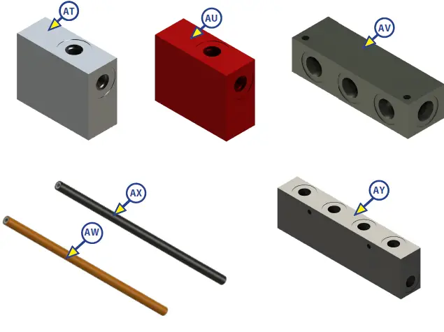
| Callout | Part # | Description |
| AT | 138420 | Manifold |
| AU | 138421 | Restricted Manifold |
| AV | 166078 | 8 Port Header Block |
| AW | 248654 | Orange Hose |
| AX | 248653 | Black Hose |
| AY | 194712 | 4 Position Eirc Block w/ Mounting Holes and Pass Through |
The contents of this manual are proprietary and copyright protected by Lippert Components, Inc. (“LCI”). LCI prohibits the copying or dissemination of portions of this manual unless prior written consent from an authorized LCI representative has been provided. Any unauthorized use shall void any applicable warranty. The information contained in this manual is subject to change without notice and at the sole discretion of LCI. Revised editions are available for free download from www.lci1.com
Please recycle all obsolete materials.
For all concerns or questions, please contact Lippert Components, Inc.
Ph: (574) 537-8900 | Web: lci1.com | Email: [email protected]