![]()
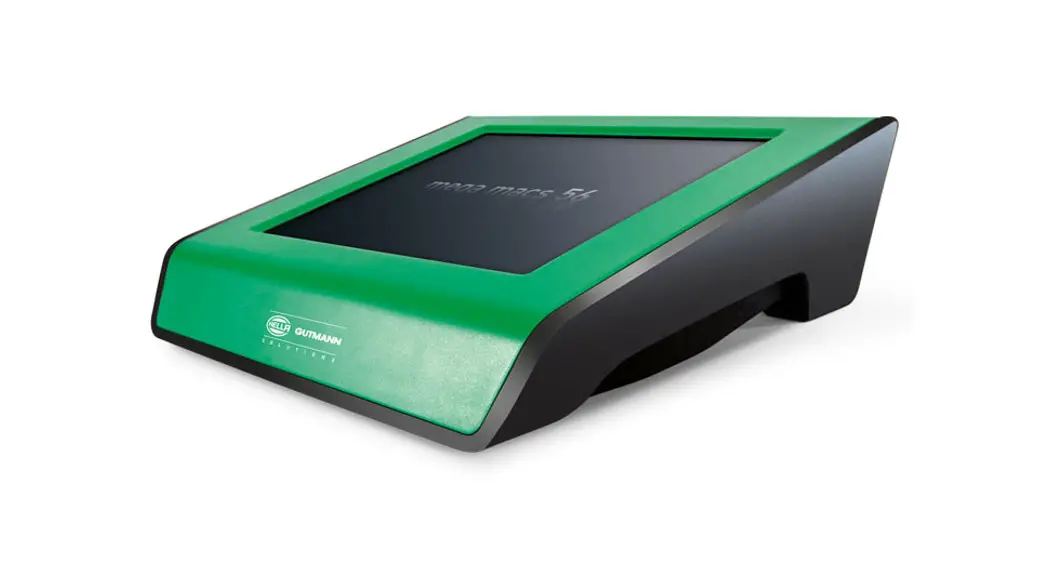
mega macs 66

Quick Start Guide
QSMM66V6500ML0222S0
460 993-60 / 02.22
About this Quick Start Guide
Translation of Original Operating Instructions
The quick start guide comprises the most important information in a clearly visible form to facilitate the start with the mega macs 66.
1.1 Notes for the Use of the Quick Start Guide
This quick start guide contains important information relevant to operator safety. Go to www.hella-gutmann.com/manuals to find all the manuals, instructions, references, and lists about our diagnostic devices, tools, and much more. Please also visit our Hella Academy under www.hella-academy.com and expand your knowledge with various online tutorials and other training courses. Please read the quick start guide entirely. Pay special attention to the first pages containing the safety instructions. They are provided solely to assure your safety when working with the device. You are recommended to read the individual work steps in the manual again while working with the device, in order to avoid danger to personnel and equipment or operating errors. The device shall be operated exclusively by personnel qualified in vehicle engineering. Information and knowledge included in this training is not explained further in this quick start guide. The manufacturer reserves the right to modify this quick start guide and the device itself without prior notice. We, therefore, recommend checking for any updates. This quick start guide must accompany the device in case of sale or other transfer. The quick start guide must be kept for the entire service life of the device and accessible at any time.
1.2 Range of Functions
The range of functions of the software may vary depending on the country, the licenses acquired, and/or the optionally available hardware. This documentation may therefore describe functions that are not available on the individual device. Missing functions can be enabled by acquiring a corresponding license subject to charge and/or additional hardware.
Safety Precautions
2.1 Safety Precautions – Risk of Injury
 | When working on the vehicle, there is a risk of injury through rotating parts or rolling of the vehicle. Therefore regard the following: • Prevent the vehicle from rolling. • Additionally place gear selector lever of AT vehicles to park position. • Deactivate the start/stop system to avoid an inadvertent engine startup. • Connect the device to the vehicle only when the ignition is switched off. • Do not reach into rotating components when the engine is running. • Do not run cables near rotating parts. • Check the high-voltage parts for damage. |
2.2 Safety Precautions for the mega macs 66
 | To prevent incorrect handling and consequent injuries to the user or damage to the device, observe the following: • Select functions and menus on the touch screen display only with clean fingers. Do not use a tool, e.g., a screwdriver. • Only connect the original power adapter to the power cord (supply voltage 10–15 V). • Protect the TFT LCD and the device from long periods of exposure to solar radiation. • Protect the device and the connecting cable from hot components. • Protect the device and the connecting cables from rotating parts. • Regularly check the connecting cables/accessory parts for damage (destruction of the device due to short circuit). • Connect the device exclusively according to the user manual. • Keep the device away from fluids such as water, oil, or gasoline. The mega macs 66 is not waterproof. • Protect the device from strong impacts and do not drop it. • Do not open the device on your own. Only technicians authorized by Hella Gutmann are allowed to open the device. Warranty and guarantee will be rendered void at any case of unauthorized tampering of the device or if the protective seal is damaged. • If the device malfunctions, contact Hella Gutmann or a Hella Gutmann trading partner without delay. |
2.3 Safety Precautions for Testing/Measuring Devices
 | • Perform measurements only on electric circuits that are not directly connected to the line voltage. • Never exceed the maximum permissible voltage load of 160 V alternating voltage (AC) or 200 V direct current voltage (DC) respectively. • Do not exceed the voltage limits indicated on the connecting cables. • The voltage values to be measured must be shielded extra or even twice from dangerous line voltage. The voltage limits printed on the test leads must not be exceeded. Pay attention that the allowed measuring range of 200 V/DC / 160 V is not exceeded when measuring the positive and negative voltage at the same time. • Never perform measurements on ignition systems. • Regularly check the test and measuring devices for damage. • Always connect the test and measuring devices to the measurement module (MT 66) first. • Do not touch the connections/measurement points during the measurement. |
Product Description
3.1 Delivery Contents
| Quantity | Designation | |
| 1 | mega macs 66 | 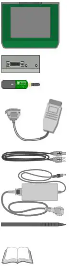 |
| 1 | diagnostic module DT 66 | |
| 1 | Bluetooth® adapter | |
| 1 | OBD and diagnostic plug | |
| 1 | USB cable for connection to a PC | |
| 1 | Power adapter and cable for the mega macs 66 | |
| 1 | Stylus | |
| 1 | HGS data carrier | |
| 1 | Quick Start Guide |
3.1.1 Checking Delivery Contents
Please check the delivery contents upon receiving your device so that complaints can be issued immediately regarding any potential damage.
Proceed as follows to check the delivery contents:
- Open the package supplied and check for completeness based on the delivery slip.
Should you identify any damage to the package, then open the package in the presence of the delivery service and check the device for hidden damage. Any transport damage to the package supplied and damage to the device shall be registered in a damage report by the delivery service. - Take the device out of the packaging.

CAUTION
The danger of short circuit due to loose parts in or on the device
The danger of destruction of the device/the automotive electronics
Never put the device into operation if you suspect that there are loose parts inside or on the device. In this case please contact the Hella Gutmann repair service or a Hella Gutmann trading partner immediately.3. Check the device for mechanical damage and shake it slightly to ensure that there are no loose parts inside.
3.2 Intended Use
The mega macs 66 is a mobile device for detecting and rectifying faults in automotive electronic systems. The device enables access to comprehensive technical data sets such as wiring diagrams and service data, set values, and descriptions of vehicle systems. A lot of this data is transferred to the device directly from the Hella Gutmann diagnostic database via an online connection. Therefore, the device must be permanently online. The device is not suitable for repairing electrical machines and equipment or home electrics. Diagnostic devices from other manufacturers will not be supported. If the device is used in a way not authorized by Hella Gutmann, the safety of the device may be influenced. The device is intended for industrial use. Outside of industrial environments, e.g., in commercial areas or in the center of a town, radio interference suppression measures may need to be taken.
3.3 Using the Bluetooth® Function
The terms of use of the Bluetooth® function may be restricted or prohibited through law or corresponding legal regulations in certain countries.
Observe the provisions in force in the respective country before using the Bluetooth® function.
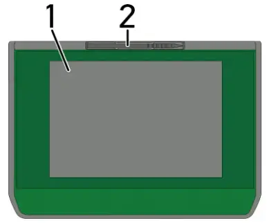
3.4 Display
| Designation | |
| 1 | TFT LCD (touch screen) |
| 2 | Stylus |
3.4.1 Operating the Device
 | NOTICE Damage or destruction of the display Never touch the display using a tool or pointed metal object. Always use the stylus or a finger. |
The device is equipped with a touch screen display. All menus and functions can be selected and/or activated by slightly touching with the stylus or the finger or just by pressing the arrow keys![]()
![]() .
.
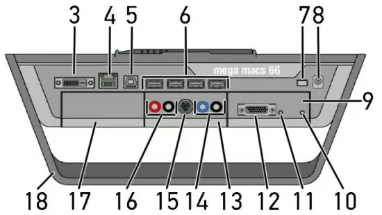
3.5 Connections of the mega macs 66
| Designation | |
| 1 | DVI-D interface Transmit digital signals with the DVI-D interface. These signals can be depicted with the help of a screen or projector. |
| 2 | Ethernet interface Use the Ethernet interface to connect the device to the following hardware: • PC • Printer • Network |
| 3 | USB device interface Use the USB device interface for data exchange between the PC and the device. |
| 4 | 4x USB host interface The USB host interfaces (USB interfaces for short) can be used to connect external devices such as a printer. |
| 5 | Main switch Switch the device off completely. |
| 6 | Power supply socket The power supply of the device and internal battery charge connection. |
| 7 | Diagnostic module DT 66 Use the DT 66 to diagnose the automotive electronics and to forward the data to the device. |
| 8 | Green LED The green LED signals the communication module is switched on and ready. |
| 9 | ON/OFF button Switch on or off the diagnostic module if it is not plugged into the module slot. |
| 10 | Parallel port Connect the ST2 plug here. |
| 11 | Measurement module MT 66 This module contains a 2-channel oscilloscope for measured variables such as the following: • Voltage • Current (with amp clamp) • Resistance |
| 12 | Oscilloscope 1 connectors Connect a test lead to Scope 1. • blue = signal • black = ground |
| 13 | ST3 connector Connect additional measuring instruments such as an amp clamp here. |
| 14 | Oscilloscope 2 connectors Connect a test lead to Scope 2. • red = signal • black = ground |
| 15 | Additional module slot Insert another module here. |
| 16 | Positioning handle Use the handle to set up the device, carry it or fix it to the steering wheel in the vehicle. |
| 17 | Internal: 1x WLAN, 2x Bluetooth® module All wireless connections are integrated in the device and are permanently switched on. |
Installation of the Hella Gutmann Drivers Package
4.1 System Requirements of Hella Gutmann Drivers
- Windows 7 SP1 or higher
- Windows administrator rights
4.2 Installation of the Hella Gutmann Drivers Package
To obtain all the data about the related vehicle provided by Hella Gutmann, the device requires a permanent online
connection and the installed driver package Hella Gutmann Drivers. To keep the connection costs down, Hella
Gutmann recommends a DSL connection and a flat rate.
- Install the Hella Gutmann Drivers on the office or repair shop PC. The driver package Hella Gutmann Drivers program is on the supplied HGS data carrier.
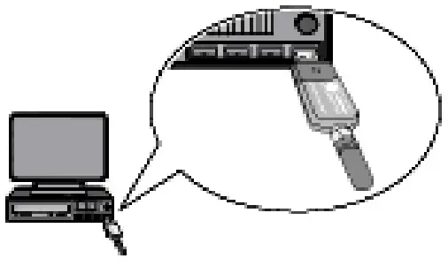
- Connect the device to a web-compatible PC.
Once the connection symbol in the top symbol bar changes from black to green, the online connection has been set up successfully and is active.
Initial Start-Up
This section gives a description of how to switch the device on and off as well as all the necessary steps for the first use of the device.
5.1 Charging the Battery
Prior to putting the device into operation, charge the battery for at least 8 to 10 h while the device is switched off.
Proceed as follows to charge the battery:
- Press in the main switch until it latches in. The electric circuit to the rechargeable battery is now closed.
- Insert the voltage supply plug into the device’s socket.
- Insert the power plug into the plug socket. The battery is being charged.
5.2 Switching on the tool
 | NOTE • When starting the device for the first time and after every software update, you need to confirm the general terms and conditions (GTC) of the Hella Gutmann Solutions GmbH. Otherwise, certain device functions will be unavailable. • The first time the device is started you need to confirm also the order processing agreement of the Hella Gutmann Solutions GmbH. It governs the handling of personal data pursuant to the GDPR. |
To switch on the tool:
- Press in the main switch until it locks into place.
The device switches to standby mode. - Lightly touch the display.
The general terms and conditions appear. - Read the general terms and conditions and confirm them at the end of the text.
The user selection window is displayed. The respective user name is saved for all data stored in the Car History.
This enables quicker identification of the mechanic who performed the repair work if a query is subsequently
made. - Double-click
 .
. - Enter the user name.
- Confirm your entry with
 .
. - Activate the Stay logged in the check box if necessary.
If the Stay logged in check box is activated, you will not need to select a user name when switching on in the future.
The order processing agreement is indicated. - Read the order processing agreement, then confirm it and agree to it at the end of the text.
- Confirm your entry with.
The input is saved automatically. The main menu appears.
Now you can start working with the device.
5.3 License Release
| NOTE In order to use the full scope of the purchased licenses you need to connect the device to the HGS server prior to the first start-up. |
Proceed as follows to connect the device with the HGS server:
- Select Contracts under > Settings in the main menu.
- Select >License<.
- Call up My licenses with
 .
.
Data download is in progress. Purchased licenses are displayed. - Switch the device off and on again.
Now you can start working with the device.
5.4 Switching off the Device
| NOTE Under normal conditions, it is sufficient to switch off the device with . |
Proceed as follows to switch off the device:
- Switch off the device with
 .
. - Observe the confirmation prompt.
- Switch off the device with. Abort the procedure with
 .
.
After switching off, the device is in standby mode.
Configuring the Device
Configure all interfaces and functions under>Settings< in the main menu.
6.1 Configuring the Interfaces
Set the interfaces for the printer, BPC-Tool, Ethernet, Bluetooth®, WLAN, and UMTS module here.
Configure all interfaces of the device under Settings > Interfaces.
If there are several possible connections to devices or tools, the fastest and most stable connection is always preferred.
The hierarchy for connection is as follows:
- Ethernet
- USB
- Bluetooth®
- WLAN
6.1.1 Configuring the Ethernet
Here you can make your network settings.
Proceed as follows to connect the device to a network (router) via Ethernet interface:
- Plugin the Ethernet cable (not included in delivery contents) in the ports of the device and the Ethernet remote station.
- Select Interfaces under > Settings in the main menu.
- Select the >Ethernet< tab.
- Open a list under IP address mode.
If >Determine automatically (DHCP)< (recommended) is set, the DHCP server of the network will assign an IP address to the mega macs 66 automatically. This option is set ex-works.
If >Determine manually< is selected, then enter a free network IP address, e.g. 192.168.246.002. under mega macs IP address. - Select >Determine automatically (DHCP)< (recommended) or >Determine manually<.
The selection will be saved automatically.
6.1.2 Configuring the Bluetooth® Adapter
Configure the Bluetooth® adapter here.
The integrated Bluetooth® module enables a wireless connection to a PC on which the driver package Hella Gutmann
Drivers are installed.
6.1.2.1 Searching for Bluetooth® Adapter
| NOTE If the device has already been delivered with a Bluetooth® adapter, both devices are already assigned to each other ex-works. |
Proceed as follows to search for the Bluetooth® adapter:
- Insert the Bluetooth® adapter into the USB port of the PC.

- Select Interfaces under > Settings in the main menu.
- Select the >Bluetooth®< tab.
- Activate the check box to be able to do the settings.
A confirmation prompt appears if WLAN was previously activated in the device. - Observe the confirmation prompt.
- Confirm the confirmation prompt with.
- Click
 for Bluetooth® adapter search.
 - Observe the info window.
- Confirm the info window with. Connection is established and the search for a Bluetooth® adapter is in progress. Once the connection from the device to the Bluetooth® adapter has been set up successfully, a list of the Bluetooth® adapters found is displayed.
- Select the requested Bluetooth® adapter. The selection will be saved automatically.
The automatically assigned Bluetooth® adapter address appears in the field Bluetooth® adapter address.
6.1.3 Searching and Installing a WLAN Interface
Proceed as follows to connect the device to a network (router) through WLAN:
- Select Interfaces under > Settings in the main menu.
- Select >WLAN<.
- Activate the check box to be able to do the settings.
A confirmation message appears if either Bluetooth® or UMTS was previously activated in the device. - Observe the confirmation prompt.
- Confirm the confirmation prompt with.
- Open a list under IP address mode.
If >Determine automatically (DHCP)< (recommended) is set, the DHCP server of the network will assign an IP address to the mega macs 66 automatically. This option is set ex-works. If >Determine manually< is selected, then enter a free network IP address, e.g. 192.168.246.002. under mega macs IP address. - Select >Determine automatically (DHCP)< (recommended) or >Determine manually<. The selection will be saved automatically.
- Create a wireless network with. The device searches for wireless networks. Once the device has successfully finished searching for wireless networks, a drop-down list of wireless networks found is then displayed.
- Select the requested wireless network.
- Regard the window with info and instructions.
- Confirm the window with info and instructions with.
- Enter the WLAN password.
- Confirm the password with. The input will be saved automatically. The following message appears if the connection to the network has been set up successfully:
• the name of the selected network under Wireless network (SSID)
• the security system of the selected wireless network under WLAN security
• the IP address of the installed Hella Gutmann Drivers under Gutmann Portal IP address - Click the symbol on the right of the header to check the connection status.
The device is connected to the Internet if the Data server is displayed under Connection and connected under WLAN. You can use the WLAN connection now.
Working with the Device
7.1 Symbols
7.1.1 General Symbols
| Symbols | Designation |
 | Switch off Switch the device off. |
| Enter Call up the selected menu. | |
| Confirm Perform the following functions: • Start the selected function. • Confirm the present entry. • Confirm your menu selection. | |
| Cancel Cancel the following functions: • Active function • Input | |
| Start Start a function or procedure. | |
| Delete Delete data or entries. | |
| Arrow keys Navigate with the cursor in menus or functions. | |
| Print Print the current window. | |
| Help Open the user manual and explanations on the individual menus or functions. | |
| Virtual keypad Open the virtual keypad for text input. | |
| Selection window Open a selection window. |
 | Select all Select all available elements. |
| Unselect all Unselect all available elements. | |
| Zoom in Zoom in the present view. | |
| Zoom out Zoom out of the present view. |
7.1.2 Symbols in the Main Menu
| Symbols | Designation |
 | Home Return directly to the main menu. |
| Vehicle Selection Select a vehicle or access the Car History. First select a vehicle to access the following functions depending on the vehicle: • Diagnostics • Vehicle Information | |
| Diagnostics Here you can find vehicle-specific ECU diagnostics, e.g.: • Trouble code readout • Parameter readout • Codings | |
| Vehicle Information Here you can find information regarding the selected vehicle, e.g.: • Assistance in finding the installation location of a component • Timing belt and service data • Technical Data • Wiring diagrams • Recall campaigns of vehicle manufacturers and importers | |
| Measurements This menu contains the 2-channel oscilloscope and the guided measurements with automatic signal evaluation. The 2-channel oscilloscope supports the following measured variables: • Voltage • Resistance • Current • Temperature • Pressure | |
| Applications Here you can find useful applications such as: • Calculation of working time on the vehicle • Glossary with an explanation of technical terms • E-mail contact to the Hella Gutmann support | |
| Optional HGS Tools Functions for linked accessory devices are stored here, e.g., for battery diagnostics. | |
| Settings Configure the device here. |
7.1.3 Symbols in the Vehicle Selection Menu
| Symbols | Designation |
 | Preselect the vehicle type Pre-filter the database according to vehicle type: • Passenger car • Motorcycle |
| Vehicle database Select a vehicle from the database, e.g., according to the following criteria: • Manufacturer • Type • Year of manufacture • Engine code | |
| Car History Call up the Car History here | |
| Display Car History files Call up a list of saved diagnostic data records on a certain vehicle. | |
| VIN identification Read out the VIN of the vehicle using the OBD plug. | |
| OBD diagnostics Here you can only start the OBD diagnostics by selecting the vehicle manufacturer and the fuel type. | |
| Page forward Go one page forward. | |
| Page back Go one page back. | |
| Information Call up additional information regarding the selected vehicle, e.g.: • Vehicle type • Engine displacement • Output • Engine code | |
| Update the Car History Update the list of vehicles in the Car History and the vehicle status here. | |
| Vehicle search in the vehicle database Search for a vehicle in the vehicle database using its VIN, its manufacturer key no., or its registration number. |
7.1.4 Symbols in the Vehicle Information Menu
| Symbols | Designation |
 | Car History This menu contains all the work done on vehicles provided that you have entered a registration number or a keyword for the vehicle selection. The data is saved under the registration number or keyword entered previously. |
| Component help Call up detailed information on the certain components, e.g.: • Engine compartment image • Component test values • Repair instruction • Component image | |
| Service data This menu contains vehicle-specific service schedules and oil change intervals. | |
| Timing belt data This menu contains the removal and installation instructions for timing belts and timing chains. | |
| Diagnostic Database This menu contains manufacturer and vehicle-specific solutions for various problematic cases. All suggested solutions are from the practice and are retrieved from the Hella Gutmann diagnostics database. | |
| Technical data Here you can find all of the data required for service and repair work, e.g.: • Timing marks • Wheel alignment data • Spark plug type | |
| Wiring diagrams This menu contains the wiring diagrams of various vehicle systems e.g.: • Engine • ABS • Airbag • Comfort | |
| Fuses/relays This menu includes the location and function of fuses and relays. | |
| Component test values This menu contains measurement and test data for components with electrical cables connected to an ECU plug. | |
| Component selection Here you can select another component. |
 | Flat rate units This menu contains the common labor rates and flat rates for diverse work on the vehicle including the service of collecting, bringing and towing assistance. |
| Component location Here you can access cabin and engine compartment images for a component. The component location is indicated by a red triangle. | |
| Cabin air filter This menu contains the demounting and installation instructions for the cabin air filter. | |
| Recall campaigns This menu contains the recall campaigns of manufacturers and importers. | |
| Battery management Here you can test the battery with the BPC-Tool. | |
| Diesel systems Here you can find the service work for diesel particulate filters. | |
| Service information This menu contains all the service information required for certain service work e.g.: • Electrics • Suspension • Accessory parts | |
| Repair instructions Here you can call up instructions for different repair work through the Hella Gutmann Drivers. | |
| Manufacturer campaigns Here you can retrieve vehicle-specific service campaigns of manufacturers via the Hella Gutmann Drivers. | |
| ADAS Advanced Driver Assistance Systems This menu contains information about the advanced driver assistance systems of the selected vehicle. | |
| Adaptive lighting systems This menu contains information about the adaptive lighting systems of the selected vehicle. | |
| e-Mobility Here you can call up additional information about electric vehicles. |
7.2 Diagnostics
7.2.1 Preparing Vehicle Diagnostics
The selection of the correct vehicle is a basic precondition for trouble-free vehicle diagnostics. The device provides assistance to simplify the selection, e.g., indicating the installation position of the diagnostic connector or vehicle identification by VIN.
The following ECU functions are possible in the >Diagnostics< menu:
- Trouble code readout
- Parameter readout
- Actuator tests
- Service reset
- Basic settings
- Codings
- Test function
Proceed as follows to prepare vehicle diagnostics:
- Select the desired vehicle under >Vehicle selection< in the main menu.
- Select >Diagnostics< in the main menu.
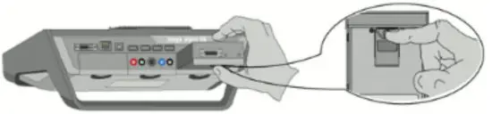
- Take the diagnostic module (DT 66) out of the mega macs 66.
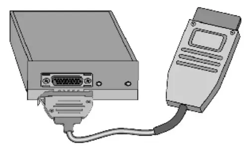
| NOTICE Short circuit and voltage peaks when connecting the ST2 and data link connector The danger of destruction of automotive electronics Switch off the ignition before connecting the ST2 and data link connector. |
4. Insert the ST2 connector into the ST2 socket of the DT 66.
 | CAUTION Pulling off of the OBD plug when operating the clutch Risk of injury or material damage Proceed as follows before starting: 1. Apply the parking brake. 2. No gear is engaged. 3. Regard the window with info and instructions. |
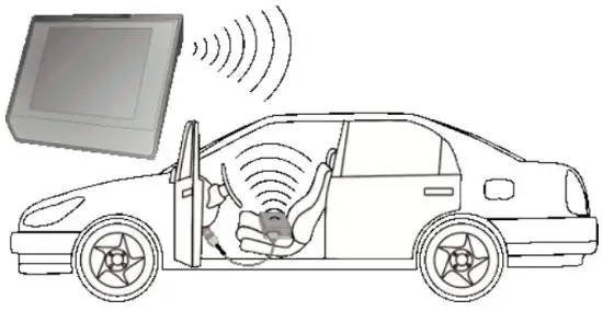
5. Insert the diagnostic plug into the vehicle’s diagnostic connector and place the DT 66 inside the vehicle cabin.
6. Select >Diagnostics< in the main menu. Now you can select the type of diagnostics.
7.2.2 Performing Diagnostics
Proceed as follows to perform diagnostics:
- Perform steps 1 to 5 as described in section Preparing Vehicle Diagnostics (Page, Seite, Page, Page, Pagina, Página, Pagina, Strona, Side, Sida, Página, Sayfa, Strana, Oldal, Sivu, Pagina, Strana, and Σελίδα 51).
- Use to select the requested diagnostic process under Function, Assembly, and System.
- Observe the information window, note window, and instruction window as applicable.
- Start the communication with
 . The diagnostic procedure between the diagnostic device and DT 66 takes place via Bluetooth®. The connection to the
DT 66 is established if the symbolchanges from black to green.
- Repair the vehicle. Then clear the saved trouble codes from the vehicle system.
7.3 Calling Up Vehicle Information
Here you have an overview of the following vehicle information:
- Car History
- Component help
- Service data
 | NOTE You require an online connection if you wish to access all available information. |
Proceed as follows to call up vehicle information:
- Select >Vehicle information< in the main menu.
- Select the requested type of information using the symbols. Certain types of information may not be available depending on the selected vehicle.
7.4 Oscilloscope
| NOTE The use of the measuring technology menu requires the optionally available measurement module (MT 66). |
Use the oscilloscope for measuring and/or depicting the following measured variables:
- Voltage
- Current
- Resistance
- Temperature
- Pressure
Current measurements are allowed exclusively with the clamp meter from Hella Gutmann. Depending on the required measurement, different clamps are to be used.
Only use the Hella Gutmann infrared thermometer for temperature measurements. Pressure measurements require the Low-Pressure Diagnostic Kit (LPD kit) of Hella Gutmann. A light blue bar in the top toolbar indicates how much of the memory space reserved for this purpose in the Car History has been used. If the blue bar is complete, the first data of the present measurement will be removed from the memory and the free capacity is filled with new data.
| CAUTION Overvoltage Fire hazard/danger of damage to the device and its surroundings Comply with the max. permitted voltage load of the oscilloscope channels |
7.4.1 Performing Oscilloscope Measurements
Proceed as follows to perform oscilloscope measurements:
- Select >Measurements< in the main menu.
- Select the >Oscilloscope< tab.
NOTE
The measured variable Voltage is supported only for the oscilloscope channels 2 and 4.The window for measured variables and channels appears.
- Plug in the test and/or signal cable into the MT 66.
- Connect the test lead to the component in question if necessary.
- Where necessary, connect the signal cable to the infrared thermometer of Hella Gutmann or the LPD kit.

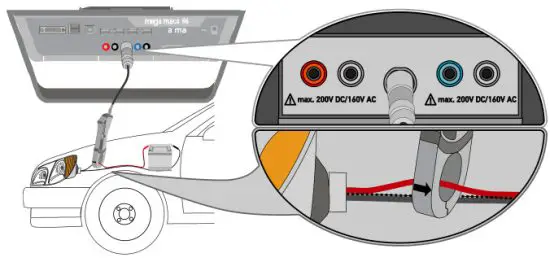
- Should you use the green amp clamp (CP 40), black amp clamp (CP 200), or blue amp clamp (CP 700), then connect it with the arrow pointing towards the battery around all positive cables, or with the arrow pointing away from the battery around all negative cables respectively.
- Activate the check box for the desired measured variable and the oscilloscope channel.
- Confirm the selection with. Measurement will be started.
- Use


 and to set the time and measured variable ranges. The ideal measuring range of the device can alternatively be determined automatically with.
 - Start Auto-Set with >
HELLA GUTMANN SOLUTIONS GMBH
Am Krebsbach 2 79241 Ihringen
GERMANY
Phone: +49 7668 9900–0
Fax: +49 7668 9900–3999
[email protected]
www.hella-gutmann.com
© 2022 HELLA GUTMANN SOLUTIONS GMBH