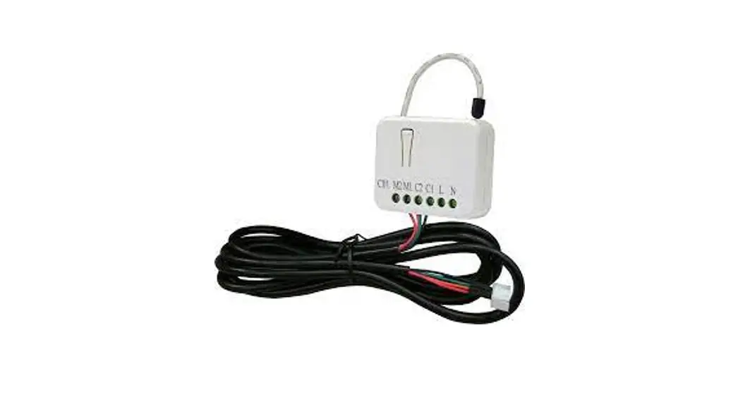
PAC01 Z-Wave JEM-A Adapter
Introduction
PAC01 is a security-enabled wireless JEM-A Adapter, based on Z-Wave Plus technology. Z-Wave Plus™ enabled devices displaying the Z-Wave Plus™
logo can also be used with it regardless of the manufacturer, and can also be used in other manufacturers’ Z-Wave ™ enabled networks. Z-Wave controller can On/Off the thermostat by sending Thermostat Setback command.
PAC01 is a transceiver which is a security-enabled device based on Z-Wave Plus technology, and it is fully compatible with any Z-Wave ™-enabled network. Since PAC01 supports Security Command Class, it can learn with a Secured enabled controller to fully utilize the device. Its functionality and supported command classes are identical when included as a secure and non-secure device.
Safety Precautions and Installation
- Avoid installing the unit in storming or raining weather.
- Be sure to isolate or switch off the power source before installing or maintenance.
- Do ensure that the power supply circuit is protected by a 16A circuit breaker or suitable equivalent fuse.
IMPORTANT
- Installation must be performed by skilled technicians who are informed about the standards and technical requirements of the appliance and its proper installation.
- Check your local codes as they apply to your situation. If the house wiring is of aluminum, consult with an electrician about proper wiring methods.
Before proceeding with the installation, TURN OFF THE POWER TO THE LIGHTING CIRCUIT AT THE CIRCUIT BREAKER OR FUSE BOX TO AVOID ELECTRICAL SHOCK.
Specification
| Rated Voltage | 220-240Vac 50Hz/60Hz 0.02A (EU) 100Vac 50/60Hz 0.02A (JP) 120Vac 60Hz 0.02A (US) |
| Operating T emperature | 0°C to 40°C (Humidity 85% max.) |
| Frequency Range | 868.40MHz & 869.85MHz / EU (PAC01-EU); |
| 908.4MHz & 916.0MHz / USA (PAC01-US); 922.50 MHz, 923.90 MHz, 926.30 MHz / JAPAN (PAC01-JP); | |
| RF Maximum PowerTransmission RangeLocation | +5dBm |
| RF Maximum PowerTransmission RangeLocation | Minimum 40 m indoor 100m outdoor line of sight |
| RF Maximum PowerTransmission RangeLocation | Indoor use only |
** Specifications are subject to change and improvement without notice.
Troubleshooting
| Symptom | Cause of Failure | Recommendation |
| The Adapter does not work and the LED off | 1. The Adapter does not connect the electrical wire properly 2. The Adapter breaks down | 1. Check power connections 2. Don’t open up the Adapter and send it for repair. |
| The Adapter cannot report to the group | 1. Not carry out association 2. Same frequency interference | 1. Carry out the association 2. Wait for a while to re-try |
For Instruction to http://www.philio-tech.com
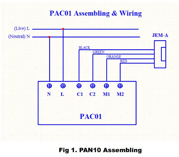
Installation
 DANGER
Danger of electrocution!
All works on the device may be performed only by a qualified and licensed electrician. Observe national regulations.
Any works introducing changes into the configuration must be always performed with disconnected voltage.
Adding to Z-Wave™ Network
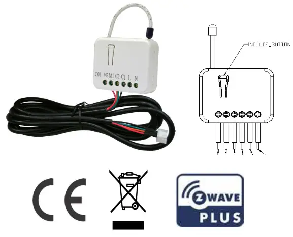
In the front casing, there is an included button with an LED indicator below which is used to carry out inclusion, exclusion, reset, or association. When the first power is applied, its LED flashes on and off alternately and repeatedly at 2-second intervals. It implies that it has not been assigned a node ID.
The table below lists an operation summary of basic Z-Wave functions. Please refer to the instructions for your Z-Wave ™ Certificated Primary controller to access the Setup function, and to Add/Remove/associate devices
| Function | Description | Annotation |
| No node ID | The Z-Wave Controller does not allocate a node ID to the Switch. | LED 2-second on, 2-second off |
| Add (Inclusion) | 1. Put your Z-Wave controller into inclusion mode by following the instructions provided by the controller manufacturer. | |
| 2. Pressing the Include button of PAC01 three times within 2 seconds will enter inclusion mode. | ||
| Remove (Exclusion) | 1. Put your Z-Wave controller into exclusion mode by following the instructions provided by the controller manufacturer. |
| 2. Pressing the Include button of PAC01 three times within 2 seconds will enter exclusion mode. | ||
| 3. Node ID has been excluded. | LED 2-second on. 2-second off | |
| Reset | 1. Pressing the Include button of PAC01 three times within 2 seconds will enter inclusion mode. | Use this procedure only in the event that the primary controller is lost or otherwise inoperable. |
| 2. Within 1 second. press the Include button of PAC01 again for 5 seconds. | ||
| 3.IDs are excluded. | ||
| SmartStart | 1. Product has a DSK string, you can key in first five-digit to increment the smart start process, or you can scan OR code. 2.SmartStart enabled products can be added into a Z-Wave network by scanning the Z-Wave OR Code present on the product with a controller providing SmartStart inclusion. No further action is required and the SmartStart product will be added automatically within 10 minutes of being switched on in the network vicinity. *notice1:The OR code can be found on the device PAC01 or in the box. |
| Association | 3. The PAC01 is an always-listening Z-Wave device, so associations may be added or removed by a controller at any time. Or If your controller requires to have the PAC01 send a ‘node information frame’ or NIF for associations, then pressing the On/Off button three times within 2 seconds will cause the PAC01 to send its NIF. | |
LED Indication
To distinguish what mode the switch is in, view from the LED for identification.
| State Type | LED Indication |
| Normal | Whenever we press the button to PAC01. the LED will be on: Otherwise, the LED is off. |
| No node ID | Under normal operation. when the Switch has not been allocated a node ID, the LED flashes on and off alternately at 2-second intervals. |
| Learning | When PACO is in learning mode. LED flashes on and off alternately and repeatedly at 2-second intervals. |
Programming
- Basic Command Class / Thermostat Setback Command Class
PAC01 will respond to BASIC and THERMOSTAT_SETBACK commands that are part of the Z-Wave system. If PAC01 is included as a secured node, it will only respond to the security encapsulation command of BASIC and THERMOSTAT_SETBACK.
1-1 BASIC_GET
Upon receipt of the following commands from a Z-Wave Controller, the Adapter will report its state to the node inquired.
| Basic Get-Command: [Command Class Basic, Basic Get] |
| Report Energy Saving Mode: [Command Class Basic, Basic Report, Value = 0] Report Comfort Mode:[Command Class Basic, Basic Report, Value = 0xFF] |
1-2 BASIC_SET / THERMOSTAT_SETBACK_SET
Upon receipt of the following commands from a Z-Wave Controller
| [Command Class Basic, Basic Set, Value = 0] : Set off. |
| [Command Class Basic, Basic Set, Value = 0xFF] : Set On |
| [Command Class Thermostat Setback, Thermostat Setback Set, properties1=2, setbackState = 128~255] : Set off. |
| [Command Class Thermostat Setback, Thermostat Setback Set, Sproperties1 ≠2 , set back state = 0~126] : Set On |
1. Z-Wave’s Groups
The Adapter can be set to send reports to associated Z-Wave devices. It supports one association group with one nodes support for grouping 1. For group 1, the Adapter will report DEVICE_RESET_LOCALLY_NOTIFICATION.
2-1 Grouping 1 Lifeline(Maximum 1 node)
2-1-1 Device reset locally notification:
When PAC01 is reset manually, it will send a DEVICE_RESET_LOCALLY_NOTIFICATION to the nodes of group ¹
Firmware update over the air (OTA)
PAC01 is based on 500 series SoC and supports Firmware Update Command Class, it can receive the updated firmware image sent by the controller via the Zwave RF media. It is a helpful and convenient way to improve some functions if needed.
Command Classes
The Switch supports Command Classes including…
| Command Class | Version | Required Security Class |
| Z-Wave Plus Info | 2 | None |
| Version | 3 | Highest granted Security Class |
| Manufacturer Specific | 2 | Highest granted Security Class |
| Security 2 | 1 | None |
| Device Reset Locally | 1 | Highest granted Security Class |
| Association | 2 | Highest granted Security Class |
| Association Group Information | 1 | Highest granted Security Class |
| Powerlevel | 1 | Highest granted Security Class |
| Basic | 1 | Highest granted Security Class |
| Firmware Update Meta Data | 4 | Highest granted Security Class |
| Thermostat setback | 1 | Highest granted Security Class |
| Supervision | 1 | None |
| Transport Service | 2 | None |
Choosing a Suitable Location
- Do not locate the Module facing direct sunlight, humid or dusty place.
- The suitable ambient temperature for the Module is 0°C~40°C.
- Do not locate the Module where exists combustible substances or any source of heat, e.g. fires, radiators, boiler, etc.
- After putting it into use, the body of the Module will become a little bit hot of which phenomenon is normal.
Disposal
 This marking indicates that this product should not be disposed of with other household wastes throughout the EU. To prevent possible harm to the environment or human health from uncontrolled waste disposal, recycle it responsibly to promote the sustainable reuse of material resources. To return your used device, please use the return and collection systems or contact the retailer where the product was purchased. They can take this product for environmentally safe recycling.
Philio Technology Corporation
8F., No.653-2, Zhongzheng Rd., Xinzhuang Dist., New Taipei City 24257, Taiwan(R.O.C)
www.philio-tech.com


