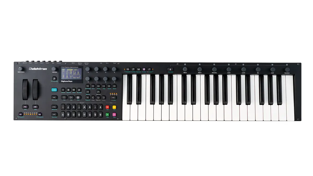
Elektron 86778 Digitone Keys Synthesizer User Guide
![]()
THANK YOU
Thank you for purchasing Digitone Keys. The Digitone Keys represents our vision of how FM synthesis can be revitalized and modernized. Here’s how: combine FM sound generation with a classic subtractive synthesis signal flow. You go from jagged chaos to mellow soundscapes in less than a second. Digitone Keys is one unique box.
Choose from multiple FM algorithms featuring carefully selected parameters. Shape the tones with powerful filters. Arrange them with the intuitive Elektron sequencer, and then round it all off with the stellar effects. Use the velocity and pressure sensitive keyboard together with the multitude of hands-on controls to take your performance to new heights. Now enjoy the most spectacular sounds, seemingly emanating from some parallel universe.
This Quick Guide guides you through the basic functions of this product. For more detailed and comprehensive information, please see the Digitone Keys User Manual that you can download on www.elektron.se.
Become the master of the digital method!
– The Elektron Team
FCC compliance statement
This device complies with part 15 of the FCC rules. Operation is subject to the following two conditions: (1) This device may not cause harmful interference, and (2) this device must accept any interference received, including interference that may cause undesired operation.
NOTE: This equipment has been tested and found to comply with the limits for a Class B digital device, pursuant to Part 15 of the FCC Rules. These limits are designed to provide reasonable protection against harmful interference in a residential installation. This equipment generates, uses and can radiate radio frequency energy and, if not installed and used in accordance with the instructions, may cause harmful interference to radio communications. However, there is no guarantee that interference will not occur in a particular installation. If this equipment does cause harmful interference to radio or television reception, which can be determined by turning the equipment off and on, the user is encouraged to try to correct the interference by one or more of the following measures:
- Reorient or relocate the receiving antenna.
- Increase the separation between the equipment and receiver.
- Connect the equipment into an outlet on a circuit different from that to which the receiver is connected.
- Consult the dealer or an experienced radio/TV technician for help.
![]() WARNING: Cancer and Reproductive Harm – www.P65Warnings.ca.gov
WARNING: Cancer and Reproductive Harm – www.P65Warnings.ca.gov
Canada
This Class B digital apparatus complies with Canadian ICES-003.
Cet appareil numérique de la classe B est conforme à la norme NMB-003.
European Union regulation compliance statement
This product has been tested to comply with the Low Voltage Directive 2014/35/EU and the Electromagnetic Compatibility Directive 2014/30/EU. The product meets the requirements of RoHS 2 Directive 2011/65/EU.
 Your product must be disposed of properly according to local laws and regulations.
Legal disclaimer
The information in this document is subject to change without notice and should not be construed as a commitment by Elektron. Elektron assumes no responsibility for any errors that may appear in this document. Elektron may also make improvements and/or changes in the products and programs described in this document at any time without notice. In no event shall Elektron be liable for any special, indirect, or consequential damages or any damages whatsoever resulting from loss of use, data, or profits, whether in an action of contract, negligence, or other action, arising out of or in connection with the use or performance of this information.
IMPORTANT SAFETY INSTRUCTIONS
- Do not use the unit near water.
- Never use aggressive cleaners on the casing or on the screen. Remove dust, dirt and fingerprints with a soft, dry and non-abrasive cloth. More persistent dirt can be removed with a slightly damp cloth using only water. Disconnect all cables before doing this. Only reconnect them when the product is safely dry.
- Install in accordance with the manufacturer’s instructions. Make sure you place the unit on a stable surface before use.
- Connect the unit to an easily accessible electrical outlet close to the unit.
- When transporting the unit, use accessories recommended by the manufacturer or the original box and padding.
- Do not install near any heat sources such as radiators, heat registers, stoves, or any other equipment (including amplifiers) emitting heat.
- This product, in combination with an amplifier and speakers or headphones, is capable of producing sound levels that can cause permanent hearing loss. Do not operate for a long period of time at a high volume level or at a level that is uncomfortable.
- Protect the power cord from being walked on or pinched particularly at plugs, convenience receptacles, and the point where they exit from the unit.
- Only use attachments/accessories specified by the manufacturer.
- Unplug this unit during lightning storms or when it is not used for an extended time.
- Refer all servicing to qualified service technicians. Servicing is required when the unit has been damaged in any way, liquid has been spilled or objects have fallen into the unit, the unit has been exposed to rain or moisture, does not operate normally, or has been dropped.
TO REDUCE THE RISK OF FIRE, ELECTRICAL SHOCK OR PRODUCT DAMAGE
- Do not expose the unit to rain, moisture, dripping or splashing and also avoid placing objects filled with liquid, such as vases, on the unit.
- Do not expose the unit to direct sunlight, nor use it in ambient temperatures exceeding 40°C as this can lead to malfunction.
- Do not open the casing. There are no user repairable or adjustable parts inside. Leave service and repairs to trained service technicians only.
- Do not exceed the limitations specified in the electrical specifications. (Available in the Digitone Keys User Manual).
SAFETY INSTRUCTIONS FOR THE POWER ADAPTER ELEKTRON PSU-3b
- The adapter is not safety grounded and may only be used indoors.
- To ensure good ventilation for the adapter, do not place it in tight spaces. To prevent risk of electric shock and fire because of overheating, ensure that curtains and other objects do not prevent adapter ventilation.
- Do not expose the power adapter to direct sunlight, nor use it in ambient temperatures exceeding 40°C.
- Connect the adapter to an easily accessible electrical outlet close to the unit.
- The adapter is in standby mode when the power cord is connected. The primary circuit is always active as long as the cord is connected to the power outlet. Pull out the power cord to completely disconnect the adapter.
- In the EU, only use CE approved power cords.
RESTART
- For a complete restart of the Digitone Keys, wait for at least 30 seconds after turning it off before turning it on again.
1. PANEL LAYOUT AND CONNECTIONS
1.1 FRONT PANEL CONTROLS

- MASTER VOLUME sets the volume for the main outputs and the headphone output.
- PITCH WHEEL applies pitch bend and other assignable modulations.
- MOD WHEEL applies assignable modulations.
- [MIDI] activates the MIDI editing mode where you can edit the MIDI tracks. A lit [MIDI] key indicates the MIDI editing mode is active. The secondary function opens the MIDI CONFIG menu.
- [FUNC] key. Press and hold [FUNC], and then press another key to access the secondary function of that key. The turquoise text on the Digitone Keys front panel shows the keys´ secondary functions.
- [SOUND BROWSER]
 opens the Sound Browser where you can preview and load Sounds. The secondary function opens the Sound Manager.
 - LEVEL/DATA sets the overall volume level of the active track. It is also used to set parameters and scroll through lists.
- Screen.
- [PATTERN MENU]
 opens the PATTERN menu, where you find pattern management. The secondary function accesses the Import/Export menu.
 - [GLOBAL SETTINGS]
 contains the management of projects, MIDI configuration, and System settings. The secondary function saves the current project.
 - [VOICE]
 opens the VOICE menu where you handle the track’s voice allocation. The secondary function toggles unison on/off.
 - [TEMPO]
 opens the TEMPO menu, where you adjust the global/pattern tempo as well as swing. The secondary function makes it possible to tap the tempo.
 - [NO] key. Used for exiting an active menu, backing one step and negating. The secondary function is a reload from the temporary save of the active pattern.
- [YES] key. Used for entering sub-menus, selecting and confirming. The secondary function is a temporary save of the active pattern.
- DATA ENTRY knobs A–H. Used for setting parameter values.
- [PARAMETER] keys access the PARAMETER pages of the active track. The color of the keys indicates if the page is active (red/blue) or inactive (off).
- LEDs indicate how many pattern pages the active pattern consists of and which pattern page is currently active. The LED flashes on the pattern page that is currently playing.
- [PAGE] selects the active pattern page, if the pattern has more than 16 steps. The secondary function accesses the SCALE menu.
- [TRACK] [T1–4] keys. Selects the active track. The secondary function mutes the track.
- The [ARROW] keys. Used for navigation and for setting parameter values. In menus, they are called [UP], [DOWN], [LEFT], and [RIGHT].
- [TRIG] keys enter or remove sequencer trigs and parameter locks, in combination with the DATA ENTRY knobs. They also select banks, and patterns, in combination with the [PTN], and [BANK] keys. The [TRIG] keys also function as a keyboard to play the Digitone Keys or to input notes chromatically into the sequencer.
- [STOP] stops the sequencer playback. The secondary function is a paste operation.
- [PLAY] starts the sequencer playback. The secondary function is a clear operation.
- [RECORD] key. Activates/deactivates GRID RECORDING mode. Press and hold [RECORD], and then press [PLAY], to activate LIVE RECORDING mode. Press and hold [RECORD], and then press [PLAY] twice to activate/deactivate quantized LIVE RECORDING. The secondary function is a copy operation.
- [BANK] selects bank A–H in combination with the [TRIG 9–16] keys. The secondary function accesses the MUTE Mode.
- [PTN] selects pattern 1–16 in combination with the [TRIG 1–16] keys. The secondary function opens the METRONOME menu.
- [MOD] key. Opens the MOD WHEEL parameter assign menu. The secondary function mutes the modulations made with the MOD WHEEL.
- [OCT-/+] transposes the [KEYBOARD] range up or down one octave. The LEDs shows the current transposition. The secondary function transposes sequencer notes up or down one octave.
- [PTCH] key. Opens the PITCH WHEEL parameter assign menu. The secondary function mutes the modulations made with the PITCH WHEEL.

- [HOLD]
 toggles the Hold function on/off. The secondary function toggles the Portamento function on/off. The LED indicates the portamento’s status.
 - [ARPEGGIATOR]
 toggles the arpeggiator on and off. The secondary function opens the ARPEGGIATOR menu.
 - [MULTI MAP]
 toggles the MULTI MAP mode on/off. The secondary function opens the MULTI MAP menu.
 - [MIDI EXT]
 toggles the MIDI CONTROLLER mode on and off. The secondary function opens the MIDI EXT menu.
 - [TRACK NOTE]
 opens the TRACK NOTE menu where you can view and edit note-related settings such as transpose, scale, and chords. The secondary function toggles chords on/off. The LED indicates the Chord functionality’s on/off status
 - [USER MODE]
 opens the USER MODE menu for the CONTROL knobs. The secondary function opens the USER MODE ASSIGN menu. Press and hold for a second to toggle between user and default parameter assignments.
 - [KEYBOARD].
- CONTROL knobs are used for setting default and user assigned parameter values.
1.2 REAR PANEL CONNECTIONS

- POWER Switch for turning the unit on and off.
- DC In Input for power supply. Use the included PSU-3b power adapter, connected to a power outlet.
- USB For connecting the unit to a computer. For MIDI-control, data transfer or Overbridge use. Use the included A to B USB 2.0 cable to connect to a computer.
- MIDI THRU/SYNC B Forwards data from MIDI IN. Can also be configured to send DIN sync to legacy instruments. Use a standard MIDI cable to connect another MIDI device in the chain.
- MIDI OUT/SYNC A, MIDI data output. Can also be configured to send DIN sync to legacy instruments. Use a standard MIDI cable to connect to MIDI IN of an external MIDI device.
- MIDI IN, MIDI data input. Use a standard MIDI cable to connect to MIDI OUT of an external MIDI device.
- CONTROL IN Inputs for sustain/expression pedals, footswitches, or CV. Use 1/4” mono phone plugs for CV signals.
- INPUT L/R Audio inputs. Use a 1/4” mono phone plug (unbalanced connection).
- TRACK OUTPUTS L/M(mono)/R Audio outputs for Track 1–4. Use L output for summed mono audio. Use either 1/4” mono phone plug (unbalanced connection) or 1/4” Tip/Ring/Sleeve phone plug (balanced connection).
- OUTPUT L/R Main audio outputs. Use either 1/4” mono phone plug (unbalanced connection) or 1/4” Tip/Ring/Sleeve phone plug (balanced connection).
- HEADPHONES Audio output for headphones. Use 1/4” Tip/Ring/Sleeve phone plug.
2. GETTING STARTED WITH DIGITONE KEYS
2.1 SETTING UP AND STARTING
Make sure you place the Digitone Keys on a stable support, with sufficient space for the cables. Switch off all devices before you connect the Digitone Keys to other devices.
- Plug the supplied DC adapter into a power outlet and connect the small plug to the 12 V DC In on the Digitone Keys.
- Connect OUTPUT L/R from the Digitone Keys to your mixer or amplifier.
- To control the Digitone Keys from a computer, connect a USB cable between the computer and the USB connector of the Digitone Keys.
- If you want to use MIDI to control the Digitone Keys, connect the MIDI OUT port of the device you wish to use as a controller to the MIDI IN port of the Digitone Keys. If you want to use Digitone Keys to control other devices using MIDI, connect the MIDI OUT port of the Digitone Keys to the MIDI IN port of the of the device you want to control.
- Connect an audio source to INPUT L/R or via USB if you want to process audio from external sources.
- Switch on all units. Press the POWER switch on the Digitone Keys to switch it on.
2.2 CHANGING SOUNDS
Press [SOUND BROWSER] and then use the LEVEL/DATA knob to scroll through the list of Sounds. Press LEVEL/DATA to load a Sound to the active track.
2.3 PLAYING THE FACTORY PRESET PATTERNS
You can find a number of preset patterns and Sounds in the Digitone Keys. Follow the instructions below to start exploring your new instrument.
- Press [BANK] and then press [TRIG 9] key to select bank A. The screen reads “BANK A : SELECT PTN”.
- Press [TRIG 1] to select the first pattern of bank A.
- Press [PLAY] to listen to pattern A01.
- Press [PTN] and then press [TRIG 2] key to select pattern A02, and so on. The new pattern starts once the previous pattern has reached its end.
White [TRIG] keys indicate pattern positions that contain data. A red [TRIG] key indicates the current active pattern. Empty patterns [TRIG] keys are unlit.
2.4 MUTING THE TRACKS
You can mute/unmute any of the sequencer tracks. You can mute/unmute all tracks simultaneously. Press [FUNC] + [T1–4] to mute a track. Press [FUNC] + [T1–4] to unmute a muted track.
2.5 TEMPO
To change the BPM setting, press the [TEMPO] key to open the TEMPO menu. Use the LEVEL/DATA knob to change tempo.
3. THE USER INTERFACE
The screen shows all the information needed for real-time interaction and editing on the Digitone Keys. The eight DATA ENTRY knob parameters shown vary depending on which parameter page you have selected. Here you can see the main interface screen of the SYN1 page.

- Bank and pattern.
- Pattern name.
- Pattern/Track transpose.
- Tempo.
- Eight track parameters. They show what parameters the DATA ENTRY knobs control, and the current parameter values.
- FM algorithm (Displayed on the SYN1 and SYN2 pages).
- Track volume level. Use the LEVEL/DATA knob to change the level.
- Track number and track type. Synth (SYN) track or MIDI (MID) track.
3.1 PARAMETER EDITING
The DATA ENTRY knobs are used to change the values of the track parameters. The positions of the parameters on the screen correspond to the physical locations of the knobs on the front panel.
- The parameters are adjusted in larger increments if you press down the DATA ENTRY knob while turning it.
- Press DATA ENTRY knob + [NO] to reset the parameter to the default value.
- Press and hold a [PARAMETER] key to see the exact parameter values on that PARAMETER page.
4. THE SEQUENCER
The sequencer stores its information in patterns. A sequencer pattern controls the playback of the synth tracks and the MIDI tracks by the trigs entered on the sequencer.
4.1 TRIGS AND TRIG TYPES
A trig is a sequencer event that you can place where you want the sequencer to perform an action on the Digitone Keys. There are two types of trigs available in the sequencer: Note trigs and Lock trigs.
- Note trigs trigger notes on synth tracks and MIDI tracks.
- Lock trigs trigger parameter locks, without triggering notes.
4.2 PATTERN RECORDING MODES
The Digitone Keys offers three main modes of inputting trigs when you create a pattern: GRID RECORDING mode, LIVE RECORDING mode, and STEP RECORDING mode. To create a new pattern, first select an empty pattern slot in one of the banks.
4.3 GRID RECORDING MODE
GRID RECORDING is a method of composing where you use the [KEYBOARD] and [TRIG] keys to add trigs in the pattern grid.
- Press [TRACK 1–4] to select the track and then press [RECORD] to enter GRID RECORDING mode. A lit [RECORD] key indicates an active GRID RECORDING mode.
- Use the [TRIG] keys to place note trigs on the sequencer. Use [TRIG] + [KEYBOARD] to add note trigs with specific note values and chords. To add a lock trig, press [FUNCTION] + [TRIG]. You can add lock trigs on any sequencer step. Press the [TRIG] key again to remove a previously placed trig.
- Select another track, and add note trigs and lock trigs.
- Press [PLAY] to listen to the sequence.
4.4 LIVE RECORDING MODE
LIVE RECORDING mode is the second method of adding trigs to the tracks. In this recording mode, the [KEYBOARD] and the [TRIG] keys are played in real time to input trigs to the tracks. You can also turn the DATA ENTRY knobs to enter lock trigs with parameter locks.
- Press and hold [RECORD], then press [PLAY] to enter LIVE RECORDING mode. The sequencer starts to play, and the [RECORD] key starts to flash red.
- Press the [KEYBOARD] or the [TRIG] keys and turn the DATA ENTRY knobs to enter trigs in real time. The [TRIG] key pressed determines the pitch value of the note trig.
- Press [PLAY] to exit LIVE RECORDING mode while keeping the sequencer playing. GRID RECORDING mode is activated if you press [RECORD] while LIVE RECORDING mode is active.
4.5 STEP RECORDING MODE
STEP RECORDING is a quick and straightforward method of placing trigs on the sequencer. In this recording mode, you insert notes by pressing the [TRIG] keys or the [KEYBOARD] (or via an external MIDI controller). The sequencer then captures the note and automatically advances to the next step.
- Press [RECORD] + [STOP] to enter STEP RECORDING mode. The [RECORD] key starts to double-blink red.
- Press a [TRIG] key to select the active step to where you want to start to add trigs.
- Play the [KEYBOARD] or press [FUNC] + [TRIG] to add a note trig to the selected step. The active step automatically advances to the next step.
- To remove a trig or to add a rest (no trig), press the [TRIG] key for the trig that you want to remove or add a rest to, and then press [NO].
4.6 PARAMETER LOCKS
Parameter locks enable all sequencer trigs to have their unique parameter values. The note trigs of a synth track can, for example, have different a pitch, velocity or length settings. It is possible to parameter lock all parameters found on the PARAMETER pages.
Documents / Resources
 | elektron 86778 Digitone Keys Synthesizer [pdf] User Guide 86778, Digitone Keys Synthesizer |
