![]() WallSwitch Wireless ON OFF Relay
WallSwitch Wireless ON OFF Relay
User Manual
WallSwitch is a wireless indoor power relay featuring a power consumption meter.
The miniature body of the device is adapted for installation in a European-type socket.![]() Regardless of the type of electrical circuit, only a qualified electrician should install WallSwitch!
Regardless of the type of electrical circuit, only a qualified electrician should install WallSwitch!
WallSwitch operates only within the Ajax security system (integration into third-party security systems is not provided), communicating with a hub via the protected Jeweller
protocol. The communication range is up to 1,000 meters in the line of sight.
Use scenarios to program actions of automation devices (Relay, WallSwitch, or Socket) in response to an alarm, Button press, or schedule. A scenario can be created remotely in the Ajax app.
How to create and configure a scenario in the Ajax security system
The Ajax security system can be connected to the central monitoring station of a security company.
Buy power relay WallSwitch
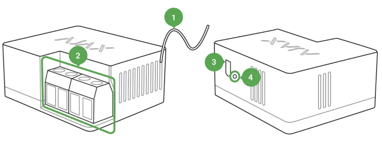
Functional Elements
 Antenna
- Terminal blocks
- Functional button
- Light indicator
 Antenna
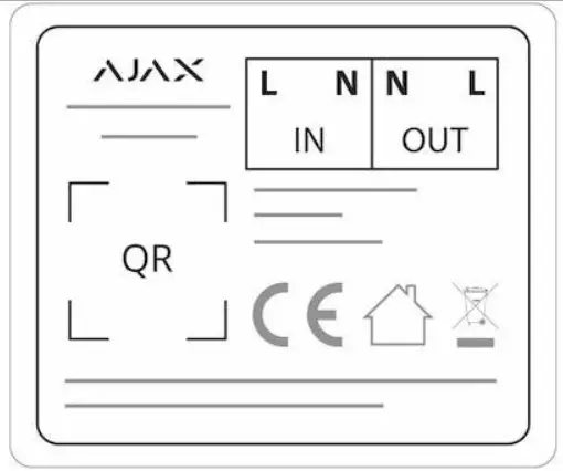
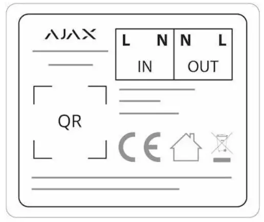
IN terminals:
- L terminal — power supply phase terminal.
- N terminal — power supply neutral terminal.
OUT terminals:
- N terminal — connected device neutral output contact terminal.
- L terminal — connected device phase output contact terminal.
Operating Principle
WallSwitch input terminals are connected to the grid, and the output terminals are connected to the socket or electrical appliance/system. WallSwitch closes/opens the electric circuit, controlling the power supply by the command of the security system user through the Ajax app. The state of WallSwitch contacts can be switched manually: by holding the function button for 2 seconds. To make WallSwitch react to alarm or schedule automatically, you can configure a scenario.
WallSwitch features a protection system against voltage surges beyond the range of 184V – 253V or overcurrent above 13А. In this case, the power supply is interrupted, resuming after normalizing the voltage and current values.
The maximum resistive load on the relay is 3 kW.
You can check the power usage by the electrical appliance connected via WallSwitch through the app. There is a power consumption meter.
WallSwitch, with rmware version 5.54.1.0 and higher, can operate in pulse or bistable mode. With this rmware version, you can also select the normal relay contact state:
Normally closed (NC) — the contacts open when the relay is activated and closed when the relay is inactive.
Normally open (NO) — the contacts close when the relay is activated and open when the relay is inactive.
WallSwitch, with the rmware version below 5.54.1.0, only works in bistable mode with a normally open contact.
How to nd out the rmware version of the device?
![]() At low loads (up to 25 W), current and power consumption indications may be displayed incorrectly due to hardware limitations.
At low loads (up to 25 W), current and power consumption indications may be displayed incorrectly due to hardware limitations.
Connecting to the hub
Before connecting the device:
- Switch on the hub and check its Internet connection (the logo glows white or green).
- Install the Ajax app. Create the account, add the hub to the app, and create at least one room.
- Make sure that the hub is not armed, and it does not update by checking its status in the Ajax app.
![]() Only users with administrator rights can add a device to the app.
Only users with administrator rights can add a device to the app.
To pair WallSwitch with the hub:
- Click Add device in the Ajax app.
- Name the device, scan it, or enter the QR code manually (located on the case and packaging), and select the room.

- Click Add — the countdown will begin.
- Press the functional button. If you can’t do this (the device is mounted in the wall), give WallSwitch at least 20 W load for ve seconds (by connecting and disconnecting a working kettle or lamp).
![]() For detection and pairing to occur, the device should be located in the coverage area of the hub’s wireless network (at the same object). The connection request is transmitted only at the moment of switching on the device.
For detection and pairing to occur, the device should be located in the coverage area of the hub’s wireless network (at the same object). The connection request is transmitted only at the moment of switching on the device.
If the device failed to pair, wait 30 seconds and then retry. WallSwitch will appear in the list of hub devices.
The device status update depends on the ping interval set in the hub settings.
The default value is 36 seconds.![]() When switching on for the first time, WallSwitch contacts are open! When deleting WallSwitch from the system, contacts open!
When switching on for the first time, WallSwitch contacts are open! When deleting WallSwitch from the system, contacts open!
States
 Devices
- WallSwitch
| Parameter | Value |
| Jeweler Signal Strength | Signal strength between hub and device |
| Connection | Connection status between hub and device |
| Routed Through ReX | Displays the status of using the ReX range extender |
| Active | State of the relay (switched on/off) |
| Voltage | The input voltage of WallSwitch |
| Current | The input current of WallSwitch |
| Power | Current consumption in W |
| Electric energy consumed | The electric power is consumed by the device connected to the relay. The counter is reset when the relay loses the power supply |
| Temporary deactivation | Displays the status of the device: active or completely disabled by the user |
| Firmware | Device rmware version |
| Device ID | Device identifier |
Settings
- Devices
- WallSwitch
 Settings
| Setting | Value |
| First eld | Device name can be edited |
| Room | Selecting the virtual room to which the device is assigned |
| Relay Mode | Selecting relay operation mode:
Settings are available with the rmware version 5.54.1.0 and higher |
| Contact status | Normal contact state
|
| Pulse duration | Selecting the pulse duration in the pulse mode: From 0.5 to 255 seconds |
| Current protection | If active, the power supply will be switched off if the current exceeds 13 A, in the inactive state the threshold is 19,8 A (or 16 A if continues for 5 seconds) |
| Voltage protection | Opens the menu for creating and configuring scenarios Learn more |
| Scenarios | Switches the device to the Jeweller signal strength test mode |
| Jeweler Signal Strength Test | Opens the WallSwitch User Manual |
| User Manual | Opens the WallSwitch User Manual |
| Temporary deactivation | Allows the user to deactivate the device without removing it from the system. The device will not execute system commands and participate in automation scenarios. All notifications and alarms of the device will be ignored Please note that a deactivated device will save its current state (active or inactive) |
| Unpair Device | Disconnects the relay from the hub and deletes its settings |
Indication
The WallSwitch light indicator can light green depending on the device’s status.
When not paired with the hub, the light indicator blinks periodically. When the functional button is pressed, the light indicator lights up.
Functionality testing
The Ajax security system allows for conducting tests for checking the functionality of connected devices.
The tests do not start immediately but within a period of 36 seconds when using default settings. The test time starts depending on the settings of the detector ping interval (the Jeweller menu in the hub settings).
Jeweler Signal Strength Test
Installation of the Device
![]() Regardless of the type of electrical circuit, only a qualified electrician should install WallSwitch!
Regardless of the type of electrical circuit, only a qualified electrician should install WallSwitch!
WallSwitch is designed for installation inside a socket box with a diameter of 50 mm and more and a depth of no less than 70 mm. The relay can also be installed within extension cords and other circuits powered by 230 V.
The communication range with the hub in the line of sight is up to 1,000 meters.
Take this into account when choosing the location for WallSwitch.
If the device has a low or unstable signal strength, use the.
ReX radio signal range extender
Installation process:
- De-energize the cable to which WallSwitch will be connected.
- Connect the grid wire to the WallSwitch terminals according to the following scheme:

- Connect a socket using bundled connecting wires or an electrical appliance using a wire with the sucient cross-section to WallSwitch. It’s recommended to use wires with a cross-section of 1.5 – 2 mm².
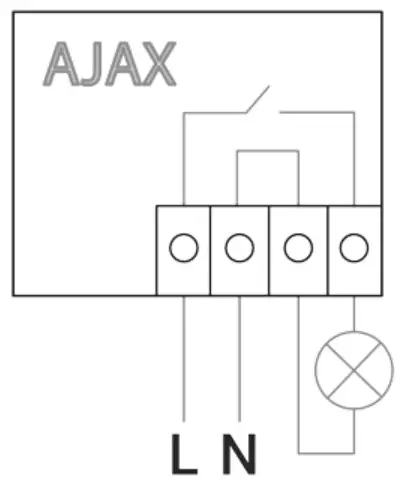
![]() Do not connect more than 3 kW load to WallSwitch. When connecting the load, strictly observe the connection diagram since an incorrect connection may cause the device to malfunction and/or damage the property.
Do not connect more than 3 kW load to WallSwitch. When connecting the load, strictly observe the connection diagram since an incorrect connection may cause the device to malfunction and/or damage the property.
When installing WallSwitch in the box, lead out the antenna and place it under the plastic frame of the socket. The bigger the distance between the antenna and metal structures, the lower the risk of interfering (and impairment) with the radio signal.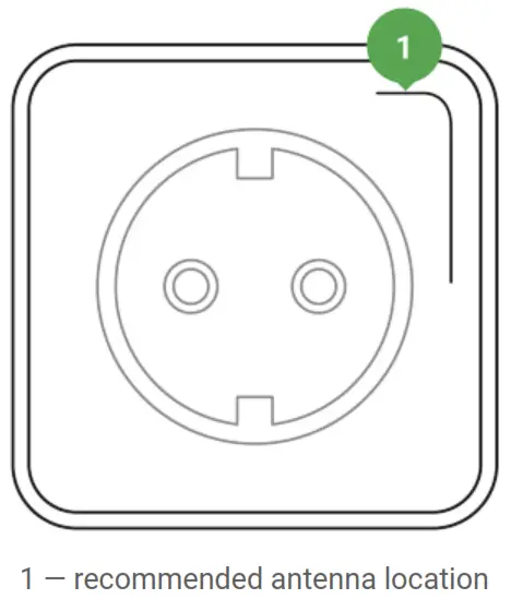
![]() Do not shorten the antenna! Its length is optimal for operation within the used radio frequency range!
Do not shorten the antenna! Its length is optimal for operation within the used radio frequency range!
During the installation and operation of WallSwitch, follow the general electrical safety rules and the requirements of electrical safety regulatory acts.![]() It is strictly forbidden to disassemble the device. Do not use the device with a damaged power cable.
It is strictly forbidden to disassemble the device. Do not use the device with a damaged power cable.
Do not install the WallSwitch:
- Outdoors.
- In metal wiring boxes and electrical panels.
- In places with temperature and humidity exceeding the permissible limits.
- Closer than 1 m to a hub.
Maintenance
The device does not require maintenance.
Tech specs
| Actuating element | Electromagnetic relay |
| The service life of the relay | 200,000 switching-ons |
| Supply voltage | 110 – 230 V AC ± 10% 50/60 Hz |
| Voltage protection | For 230 V mains: max — 253 V, min — 184 V For 110 V mains: max — 126 V, min — 77 V |
| Maximum load current | 13 А |
| Maximum current protection | Yes, 13 A |
| Power output (resistance load 230 V) | Up to 3 kW |
| Operating modes |
|
| Pulse duration | 0.5 to 255 seconds (rmware version is 5.54.1.0 or higher) |
| Electricity meter function | Yes |
| Power consumption | Yes: current, voltage, |
| parameters control | consumed power |
| The power consumption of the device in the standby mode | Less than 1 W |
| Frequency band | 868.0 – 868.6 MHz or 868.7 – 869.2 MHz depending on the region of sale |
| Compatibility | Operates with all Ajax hubs, and range extenders |
| Maximum RF output power | Up to 25 mW |
| Modulation | GFSK |
| Radio signal range | Up to 1,000 m (any obstacles absent) Learn more |
| Shell protection rating | IP20 |
| Operating temperature range | From 0°С to +64°С |
| Maximum temperature protection | Yes, 65°C |
| Operating humidity | Up to 75% |
| Overall dimensions | 39 × 33 × 18 mm |
| Weight | 30 g |
| Service life | 10 years |
Complete Set
- WallSwitch
- Connecting wires — 2 pcs
- User Manual
Warranty
Warranty for the “AJAX SYSTEMS MANUFACTURING” LIMITED LIABILITY COMPANY products is valid for 2 years after the purchase.
If the device does not work correctly, you should first contact the support service— in half of the cases, technical issues can be solved remotely!
The full text of the warranty
User Agreement
Technical support:
[email protected]
References
 End user agreement - Ajax Systems
-
Jeweller radio technology | Ajax Systems
-
Current product lines of the Ajax security system
-
Current product lines of the Ajax security system
-
Current product lines of the Ajax security system
-
Wireless panic button with control mode | Ajax Systems
-
ReX — Intelligent radio signal range extender | Ajax Systems
-
Ajax WallSwitch — Wireless power relay with energy monitor
-
Jeweller and Wings radio protocols in the Ajax security system
-
Software | Ajax Systems
-
Ajax devices standards compliance list
-
Warranty - Ajax Systems
-
How to find out the device firmware version | Ajax Systems Support
-
How to create and configure a scenario in the Ajax system | Ajax Systems Support
-
What is Jeweller Signal Strength Test | Ajax Systems Support


