INOR 70CFGUSX01 Ex-Certified Configuration Kit for Transmitters
CONFIGURATION KIT
General safety notes
CAUTION!
The USB interface ICON-X is an Ex-approved product that is intended to be used for all type of transmitters when in safe areas.
General information
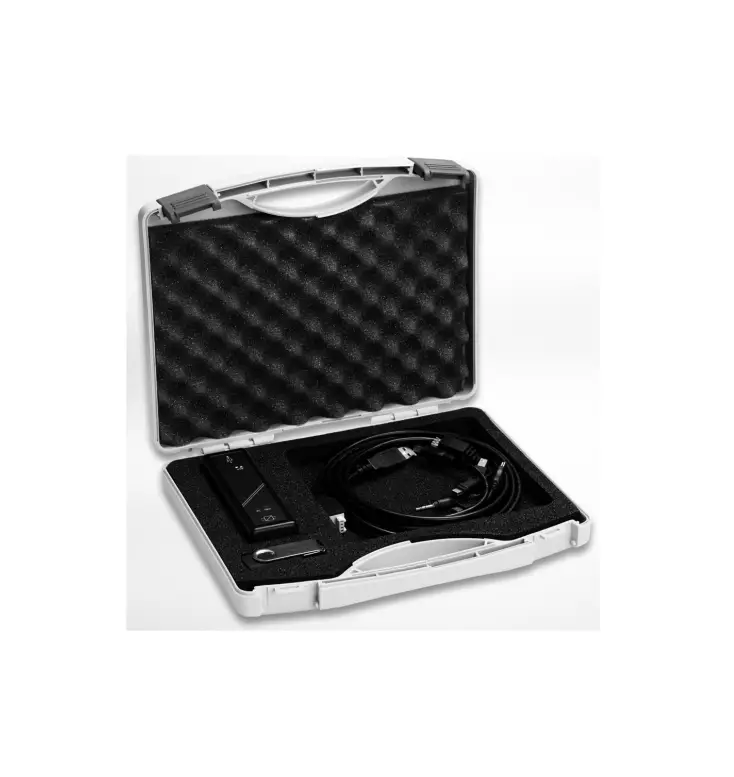
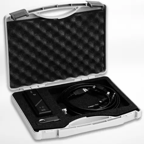
- The configuration kit includes all necessary software and hardware for configuration of the temperature transmitters from a PC´s USB port.
- Configuration starts from the main program Con Soft. Con Soft will identify the connected transmitter and open the necessary configuration software.
- ICON-X configuration kit consists of:
- USB interface ICON-X
- USB cable (connection between PC and USB interface)
- Adapter cables (connection between USB interface and transmitter)
- Software and drivers on a USB memory stick
- The configuration kit is compatible with Windows XP (SP3), Windows Vista, Windows 7, Windows 8, Windows 8.1 and Windows 10.
- DANGER!
ICON-X is the Ex-approved connection between a PC USB interface and an INOR Ex-approved transmitter. It may be used with non-Ex approved Inor transmitter as well. The ICON-X must not be used in hazardous area. Consult the user instruction and Ex certificate of the used transmitter regarding the possibility to configure “online” if the input of the transmitter is connected to hazardous area. - DANGER!
ICON-X contains no reparable parts. Repairing or fixing the circuit or replacing components may impact the intrinsic safety. - CAUTION!
Only one transmitter may be connected at a time.
Certifications
- EU directive compliance
- The USB interface, used with the provided cables, is CE-marked and complies with the EMC directive 2014/30/EU based on the harmonised standard EN 61326-1:2013, the ATEX-directive 2014/34/EU based on the harmonised standards EN 60079-0:2012 including A11 and EN 60079-11:2012. and the ROHS directive 2011/65/EU, based on the harmonised standard EN 50581:2012. For more information refer to the Declaration of Conformity, which can be found in the download area of the manufacturer’s website.
- For other cables than the provided and with cable length ≥ 3 m / 9.8 ft. other requirements are valid and are not covered by this EMC directive.
- Ex approvals
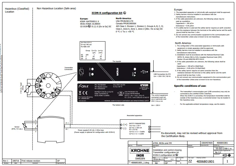
ATEX KIWA 16ATEX0011X II (1) G [Ex ia Ga] IIC IECEx IECEx KIWA 16.0005X [Ex ia Ga] IIC USA FM18US0117X AIS CL I, Div 1 and 2, GP A-D, CL I, Zn 0, 1 and 2, [AEx/Ex ia Ga] IIC
Canada FM18CA0056X - USA and Canada:
EX-approvals according to: FM 3600, ANSI/ISA 60079-0, CAN/CSA C22.2 No. 0,
CAN/CSA C22.2 60079-0, FM 3610, ANSI/ISA 60079-11, CAN/CSA C22.2 60079-11 - See also “Special conditions for safe use” in the Ex certificates in the download area of the manufacturer’s website.
- USA and Canada:
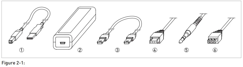
Scope of delivery
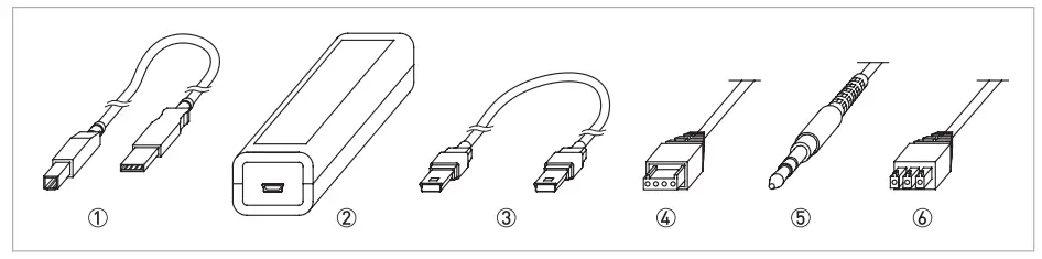
Figure 1-1: Scope of delivery
- USB communication cable (connection between PC and USB interface)
- USB interface
- Mini USB to Mini USB adapter (USB interface to transmitter)
- Mini USB to four pole rectangular connector (USB Interface to transmitter)
- Mini USB to 3.5 mm tele plug connector (USB Interface to transmitter)
- Mini USB to three pole rectangular connector (USB Interface to transmitter)
Nameplate
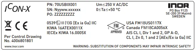
- PN = Part number
- SN = Serial number (yyww = year and week of manufacturing)
- PO = Batch number
Technical data
- Operating conditions
Ambient temperature 0…+50°C / +32…+122°F Storage temperature -20…+70°C / -4…+158°F Humidity (non-condensing) 0…90% RH - Installation
Installation For detailed information, refer to chapter “Installation”. Dimensions USB interface Length: 114 mm / 4.49″; width: 36 mm / 1.42″ ; heigth: 26 mm / 1.02″
- Electrical connection
Power supply PC’s USB port; 5 VDC; 74 mA max. Galvanic isolation 1500 VAC Input (PC to USB interface) USB cable type A to type B Output (USB interface to transmitter) Changeable adapter cables - System requirements
Windows Windows XP (SP3), Vista, 7, 8, 8.1 or 10 Display resolution Minimum 800×600 Free hard disk space 185 MB PC Port 1x USB 1.1 or higher port type A Ex parameters Comm.port (PC connection) Um = Vmax : 250 V AC/DC Output port (to transmitter) Uo = Voc : 9.4 VDC Io = Isc : 96 mA Po : 680 mW
INSTALLATION
General safety notes
CAUTION!
The USB interface ICON-X is an Ex-approved product that is intended to be used for all type of transmitters when in safe areas.
Safety Diagram
DANGER!
The transmitter’s communication port (USB connection) may only be connected to the certified ICON-X interface. When the ICON-X is connected, the temperature transmitter shall be outside of the hazardous area; a connected sensor may be located in the hazardous area.
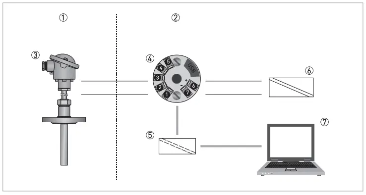
- Hazardous Area
- Safe Area
- Temperature Sensor
- Temperature Transmitter
- ICON-X USB interface
- Ex-approved Power Supply/ Zener barrier 7 PC
Installation of USB interface drivers
- Before you can use the USB interface you must install the USB drivers on your PC. The setup file includes drivers for the USB interface and can be installed manually when running the setup file. The drivers can also be installed automatically by using Windows
- Update if the computer supports this function.
- For detailed information refer to section “Installation guide for Con Soft and USB-Interface drivers”.
- All software, USB drivers and installation guides can also be downloaded from the website.
Installation of configuration software Con Soft
- All necessary software for configuration are included on the memory stick or can be downloaded from the website of the manufacturer.
- For detailed information refer to section “Installation guide for Con Soft and USB-Interface drivers”.
- All software, USB drivers and installation guides can also be downloaded from the website.
Description of USB interface ICON-X
The USB interface ICON-Xis powered from the PC´s USB port. There are three LED indicators on the USB interface: “USB”, “PC” and “DEV”. They are indicators to make the understanding of the communication between PC and transmitter easier. Their functions are described below:
- “USB” LED indicates data transfer. It lights during data transfer, otherwise it is off.
- “PC” LED indicates connection between configuration program and PC. It is green only during reading or writing to transmitter.
- “DEV” LED indicates the transmitter connection status. If it’s green, the connected transmitter is detected by the USB interface. Flashing green indicates that the USB interface is waiting for a new transmitter from the same product family, e.g. changing to a new device. When it´s red no transmitter is detected by the USB interface and any sort of transmitter can be connected to the USB interface.
CAUTION!
The installation guide must be read prior to installation.
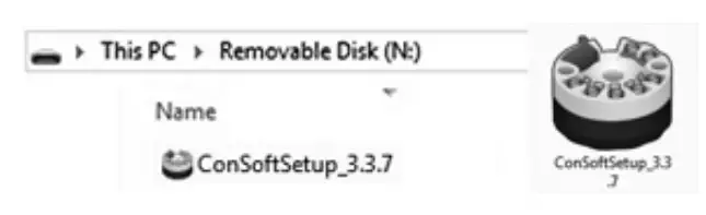
Installation guide for Con Soft and USB-Interface drivers
Locate the executable setup file “Con Soft Setup”. Double click on the file to start the installation process and follow the instructions on screen.
Troubleshooting
| Error message | Action |
| Error message “USB Interface is not installed. The program will not work.” displayed when starting ConSoft. | Install drivers for the USB interface. |
| Error message “USB Interface:s hardware and/or software should be updated.” appears in ConSoft. | Contact us for update of your USB interface. |
| Error message “Unable to install because a newer version of this product is already installed.” is displayed during installation of ConSoft. | A newer version of ConSoft is already installed on the computer. If you still want to install the older version, uninstall ConSoft through “Control Panel – Add or Remove Programs”. |
Disassembling and recycling of Transmitter configuration kit ICON-X
This section describes (in short) the instructions of handling and disassembling the device when it’s reached EOL (end of life) or is disposed of after usage. The information given is sufficient to gather the most important parts of the device (by the end-user) which can be used for recycling.
Content of USB configuration kit ICON-X
| Item No | Item Name | Weight (g) | Weight (lb) |
| 1 | USB communication cable (connection between PC and USB interface ICON-X) | 42 | 0,09 |
| 2 | USB Interface ICON-X | 63 | 0,14 |
| 3 | Mini USB to Mini USB adapter (USB interface ICON-X to transmitter) | 17 | 0,04 |
| 4 | Mini USB to four pole rectangular connector (USB interface ICON-X to transmitter) | 23 | 0,05 |
| 5 | Mini USB to 3.5 mm tele plug connector (USB interface ICON-X to transmitter) | 19 | 0,04 |
| 6 | Mini USB to three pole rectangular connector (USB interface ICON-X to transmitter) | 24 | 0,05 |
| 7 | USB memory | 15 | 0,03 |
| 8 | Case polypropylene | 300 | 0,66 |
| 9 | Foam cushioning PU | 20 | 0,04 |
| Total | 521 | 1,15 |
- Table 2-1: USB configuration kit ICON-X
- Item 1 and 3 – 7; sorted as electrical waste
- Item 2; sorted according to chapter 2.9
- Item 8 and 9; sorted as plastic.
Disassembling and recycling of USB Interface ICON-X
- DANGER!
The device MUST be disconnected from mains power before disassembling. - Wear personal protective equipment. Make sure you use a steady workplace/bench to do the disassembly actions.
- CAUTION!
Before disassembling the device, make sure you have the proper tools needed:- Torx Screwdriver T9
- Philips head Screwdriver #1
Item 2 (Table 2-1) USB Interface ICON-X consists of
| Item No | Item Name | Weight (g) | Weight (lb) |
| 1 | Label, upper side polyester | 0 | 0 |
| 2 | Label, bottom side polyethylene | 0 | 0 |
| 3 | General purpose ABS plastic package box (UL94-HB) | 38 | 0,08 |
| 4 | PCB Glass fiber reinforced Epoxy 10,6×2,9 cmm2 | 22 | 0,05 |
| 5 | Cover Screws threaded, 2 pieces (4×3/4 self-tapping oval head 19,1 mm) | 2 | 0 |
| 6 | Sealing washer, 2 pieces | 0 | 0 |
| 7 | PC Board Screws, 2 pieces (4×1/4 self-tapping oval head 6,4 mm) | 0 | 0 |
| Total | 63 | 0,14 |
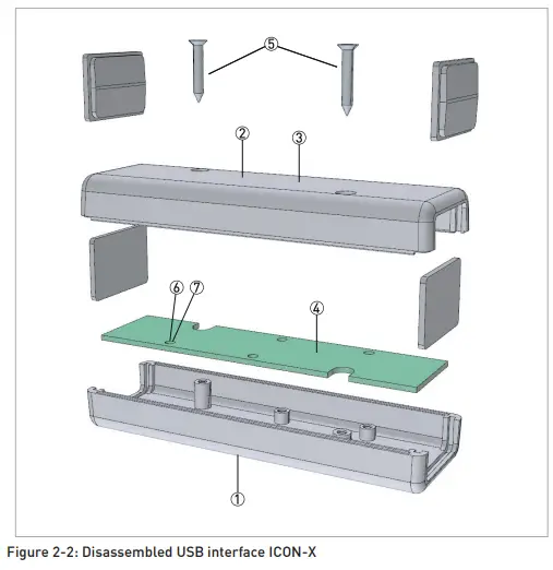
USB Interface ICON-X may be separated into smaller parts. Items are numbered according to the Table 2-2.
- Disassemembling USB Interface ICON-X
- Disconnect connection to the PC (if any connected).
- Disconnect temperature transmitter (if any connected).
- Remove the labels (polyester and polyethylene) sorted as plastic.
- By unscrewing of the two threaded screws (item 5) from the bottom cover of the housing, upper part of Item 3(in Table 2) can be separated from bottom part.
- Lift up front and rear panel of the item 3. They are sorted as plastic.
- By unscrewing of the two threaded screws(item 7) on the PCB(item 4) separate the bottom cov-er of the housing – Item 3 and PCB(item 4).
- Items 1, 2 and 3 are sorted as plastic.
- Item 4 sorted as electronic waste.
- Item 6(Sealing washer) sorted as ordinary waste.
- Item 5 and 7 are sorted as metal waste.
Installation and control drawing
ABOUT COMPANY
- Inor Process AB
- PO Box 9125
- SE-200 39 Malmö
- Sweden
- Phone: +46-(0)40-312 560
- Fax: +46-(0)40-312 570
- E-mail: [email protected]
- Subsidiaries
- Inor Transmitter Oy Unikkotie 13
- FI-01300 Vantaa
- Finland
- Phone: +358-(0)10-4217900
- Fax: +358-(0)10-4217901
- E-mail: [email protected]
- Inor Transmitter GmbH Am See 24
- D- 47279 Duisburg
- Germany
- Phone: +49-(0)203 7382 762 0
- Fax: +49-(0)203 7382 762 2
- E- mail: [email protected]
- Web: www.inor-gmbh.de
- Inor North America
- 7 Dearborn Road
- Peabody, MA 01960
- United States
- Phone: +1 978 826 6900
- Fax: +1 978 535 1720
- E-mail: [email protected]
- Web: www.inor.com


