FSV-75 Half-Circle Color Scanning Sonar
![]()
Installation Manual
HALF-CIRCLE COLOR SCANNING SONAR
Model FSV-75/FSV-75-3D
 SAFETY INSTRUCTIONS
The installer must read the safety instructions before attempting to install the equipment.![]() DANGER Indicates a potentially hazardous situation which, if not avoided, will result in death or serious injury.
DANGER Indicates a potentially hazardous situation which, if not avoided, will result in death or serious injury.![]() WARNING Indicates a potentially hazardous situation which, if not avoided, could result in death or serious injury.
WARNING Indicates a potentially hazardous situation which, if not avoided, could result in death or serious injury.![]() CAUTION Indicates a potentially hazardous situation which, if not avoided, may result in minor or moderate injury.
CAUTION Indicates a potentially hazardous situation which, if not avoided, may result in minor or moderate injury.
| Warning, Caution |
| Prohibitive Action | |
| Mandatory Action |
DANGER![]() Keep away from raise/lower shaft in hull unit when it is moving.
Keep away from raise/lower shaft in hull unit when it is moving.
Gears will cause serious injury. In case of an emergency, press the EMERGENCY STOP button to stop the raising or lowering of the transducer.![]() Confirm that there is no person below the transducer before raising or lowering the transducer.
Confirm that there is no person below the transducer before raising or lowering the transducer.
WARNING
![]() Do not open the equipment unless totally familiar with electrical circuits and the service manual.
Do not open the equipment unless totally familiar with electrical circuits and the service manual.
High voltage exists inside the equipment, and a residual charge remains in capacitors several minutes after the power is turned off. Improper handling can result in electrical shock.
![]() Turn off the power at the main switchboard before beginning the installation.
Turn off the power at the main switchboard before beginning the installation.
Fire, electrical shock, or serious injury can result if the power is left on or is applied while the equipment is being installed.![]() Do not install the equipment where it may get wet from rain or water splash.
Do not install the equipment where it may get wet from rain or water splash.
Water can cause fire or electrical shock, or damage the equipment.
WARNING
![]() Be sure no water leaks in at the hull unit.
Be sure no water leaks in at the hull unit.
Water leakage can sink the vessel. Also, confirm that the transducer will not loosen by the ship’s vibration. The installer of the equipment is solely responsible for the proper installation of the equipment. FURUNO will assume no responsibility for any damage associated with improper installation.![]() If a steel tank is installed on a wooden or FRP vessel, take appropriate measures to prevent electrolytic corrosion.
If a steel tank is installed on a wooden or FRP vessel, take appropriate measures to prevent electrolytic corrosion.
Electrolytic corrosion can damage the hull.![]() Do not remove the hull unit brake.
Do not remove the hull unit brake.
There is a risk of the shaft falling out.![]() Install the specified transducer tank in accordance with the installation instructions. If a different tank is to be installed the shipyard is solely responsible for its installation, and it should be installed so the hull will not be damaged if an object strikes the tank.
Install the specified transducer tank in accordance with the installation instructions. If a different tank is to be installed the shipyard is solely responsible for its installation, and it should be installed so the hull will not be damaged if an object strikes the tank.
The tank or hull may be damaged if the tank strikes an object.![]() Be sure to power each unit with proper voltage.
Be sure to power each unit with proper voltage.
Connection of an improper power supply can cause fire or damage to the equipment. WARNING![]() Use only the specified power and signal cable.
Use only the specified power and signal cable.
Fire or damage to the equipment can result if a different cable is used.
CAUTION
WORKING WITH THE SONAR OIL
Precautions
- Keep the oil away from the eyes. Wear protective glasses when working with the oil. The oil can cause inflammation of the eyes.
- Do not touch the oil. Wear protective gloves when working with the oil. The oil can cause inflammation of the skin.
- Do not ingest the oil. Diarrhea or vomiting can result.
- Keep the oil out of reach of children.
- For further details, see the material safety data sheet (MSDS).
Emergency
- If the oil enters the eyes, flush with clean water for about 15 min. Consult a physician.
- If the oil contacts skin, wash with soap and water.
- If the oil is ingested, see a physician immediately.
- Keep the oil out of reach of children.
- For other information, see the material safety data sheet (MSDS).
Disposal of oil and its container
- Dispose of oil and its container in accordance with local regulations. For further details, contact the place of purchase.
Storage
- Seal container to keep out foreign materials. Store in a dark place.
CAUTION
![]() Maximum speed while the transducer is projected or being raised or lowered is as below, to prevent damage to the transducer.
Maximum speed while the transducer is projected or being raised or lowered is as below, to prevent damage to the transducer.
| Projected | Raising/Lowering |
| 18 kn | 15 know |
![]() Ground the equipment to prevent electrical shock and mutual interference.
Ground the equipment to prevent electrical shock and mutual interference.
![]() Connect the ground terminal to the ship’s ground.
Connect the ground terminal to the ship’s ground.
If the ground terminal is connected to a terminal other than the ship’s ground (ex. main engine), electrolytic corrosion may occur.![]() Do not connect/disconnect the connector while turning the power on.
Do not connect/disconnect the connector while turning the power on.
The equipment may be damaged.![]() Observe the following compass safe distances to prevent magnetically compass deviation:
Observe the following compass safe distances to prevent magnetically compass deviation:
| Unit | Standard Compass | Steering Compass |
| Processor Unit | 2.15 m | 1.35 m |
| Control Unit | 0.30 m | 0.30 m |
| Remote Controller | 0.30 m | 0.30 m |
| Transceiver Unit | 1.85 m | 1.20 m |
| Matching Box | 1.25 m | 0.80 m |
| Control Box | 1.45 m | 0.95 m |
| Extension Box | 1.35 m | 0.90 m |
| Motion Sensor | 0.50 m | 0.35 m |
![]() If the ambient temperature around the hull unit will be below 0°C, provide the sonar compartment with a heater to keep the temperature above 0°C.
If the ambient temperature around the hull unit will be below 0°C, provide the sonar compartment with a heater to keep the temperature above 0°C.
The hull unit can not work if the ambient temperature is below 0°C.![]() Do not apply substances that contain organic solvents (alcohol, thinner, etc.) to the dome.
Do not apply substances that contain organic solvents (alcohol, thinner, etc.) to the dome.
Chemical cracking may occur.
SYSTEM CONFIGURATION
SYSTEM CONFIGURATION
Compatible equipment
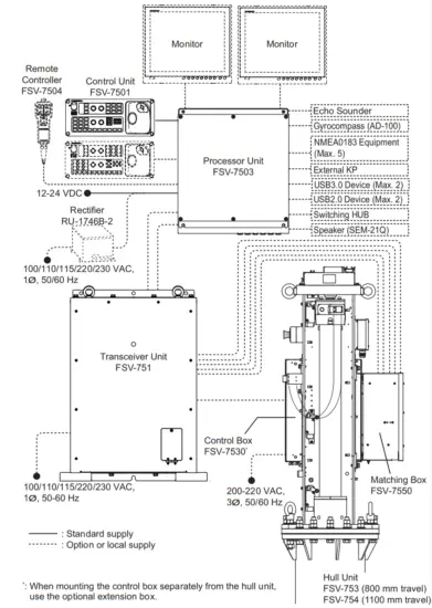
This system is compatible with the following FURUNO equipment:
| Name | Model | Remarks |
| Monitor Unit | MU-190 | Brilliance control is available with direct USB connection to the FSV-7503. The USB cable for brilliance control should be connected directly to the FSV-7503. Do not use a USB hub. |
| MU-190HD | ||
| Color LCD Sounder | FCV-1200L*1 | – |
| FCV-1200LM | ||
| FCV-1500L*1 | ||
| Fish Finder | FCV-1900*2 | |
| Hi-Res Fish Finder | FCV-1900B*2 | |
| Fish Size Indicator | FCV-1900G*2 |
*1: Requires EXIF assembly connection (available as an optional extra) at the fish finder.
*2: Connect via the FCV-1903. If a telesounder is already connected to the FCV-1900/B/G, the connection between the FSV-75 and FCV-1900/B/G is not available.
EQUIPMENT LISTS
Standard supply
| Name | Type | Code No. | Qty | Remarks |
| Control Unit | FSV-7501 | – | 1 | With 5 m or 10 m cable |
| Processor Unit | FSV-7503 | – | 1 | |
| Transceiver Unit | FSV-751 | – | 1 | |
| Hull Unit | FSV-753 | – | 1 | 800 mm travel |
| FSV-754 | – | 1100 mm travel | ||
| Matching Box | FSV-7550 | – | 1 | |
| Installation Materials | CP10-09600 | 000-036-274 | 1 | For control unit |
| CP10-09700 | 000-036-275 | 1 | For processor unit | |
| CP10-09801 | 001-538-860 | 1 | For transceiver unit | |
| CP10-10301 | 001-537-600 | 1 | For matching box | |
| Local Assembling Parts | FSV-75-T | 001-541-090 | 1 | For hull unit with the retraction tank |
| FSV-75-N | 001-541-100 | For hull unit without the retraction tank | ||
| Spare Parts | SP26-00301 | 001-080-860 | 1 | For processor unit |
| SP10-04301 | 001-538-850 | 1 | For transceiver unit | |
| SP10-04401 | 001-539-770 | 1 | For control box |
Optional supply
| Name | Type | Code No. | Remarks | |
| Control Unit | FSV-7501 | – | With 5 m or 10 m cable | |
| Extension Box | FSV-7560 | – | For separate installation of the control box | |
| Remote Controller | FSV-7504 | – | With 5 m or 10 m cable | |
| External Loudspeaker | SEM-21Q | – | ||
| Interface Unit | VI-1100A | – | For connection with FCV-1200L/ 1500L | |
| Rectifier | RU-1746B-2 | – | ||
| Attachment Flange* | OP10-50 | 001-542-280 | 150 mm height-raising | |
| OP10-51 | 001-542-290 | 250 mm height-raising | ||
| OP10-52 | 001-542-300 | 350 mm height-raising | ||
| OP10-53 | 001-542-310 | 450 mm height-raising | ||
| Main Shaft Replacement Kit | OP10-54 | 001-544-590 | For the main shaft replacement in case of a marine accident | |
| Attachment Kit` | OP10-56 | 001-551-540 | ||
| Retraction Tank | OP10-57 | 001-551-560 | For a steel vessel, 800 mm travel | |
| OP10-58 | 001-551-620 | For a steel vessel, 1100 mm travel | ||
| Installation Materials | CP10-10100 | 000-036-244 | LAN cable between pro- cessor unit and transceiver unit | 10 m |
| CP10-10110 | 000-036-245 | 15 m | ||
| CP10-10120 | 000-036-246 | 30 m | ||
| CP10-10130 | 000-036-247 | 40 m | ||
| CP10-10140 | 000-036-248 | 50 m | ||
| CP10-10150 | 000-036-722 | 100 m | ||
EQUIPMENT LISTS
| Name | Type | Code No. | Remarks | |
| 5-pair Cable | 10S2380 *10M* | 001-196-330-10 | Cable between processor unit and transceiver unit | 10 m |
| 10S2380 *20M* | 001-196-340-10 | 20 m | ||
| 1032380 *30M* | 001-196-350-10 | 30 m | ||
| 1032380 *40M* | 001-196-360-10 | 40 m | ||
| 1052380 *50M* | 001-196-370-10 | 50 m | ||
| 1052380 *60M* | 001-196-380-10 | 60 m | ||
| 1052380 *100M* | 001-196-390-10 | 100 m | ||
| Cable Assembly | 10CA10137*5M* | 001-552-210 | Cable between extension box and control box (rotation motor line) | 5 m |
| 10CA10137*10M* | 001-552-220 | 10 m | ||
| 10CA10138*5M* | 001-552-230 | Cable between extension box and control box (pitch motor line) | 5 m | |
| 10CA10138*10M* | 001-552-240 | 10 m | ||
| 10CA10139*5M* | 001-552-250 | Cable between extension box and control box (rotation resolver line) | 5 m | |
| 10CA10139*10M* | 001-552-260 | 10 m | ||
| 10CA10140*5M* | 001-552-270 | Cable between extension box and control box (pitch resolver line) | 5 m | |
| 10CA10140*5M* | 001-552-280 | 10 m | ||
| 10CA10110*5M* | 001-552-290 | Cable between transceiver unit and matching box | 5 m | |
| 10CA10110*10M* | 001-552-300 | 10 m | ||
| 10CA10147*2M* | 001-552-310 | Cable between transceiver unit and control box | 2 m | |
| 10CA10147*5M* | 001-552-320 | 5 m | ||
| 10CA10147*10M* | 001-552-330 | 10 m | ||
| HDMI-TO-DVI- L=5.3M | 001-407-180 | For connection with MU-190/MU-190HD | 5.3 m | |
| HDMI-TO-DVI- L=10.3M | 001-407-170 | 10.3 m | ||
*: Required when you install the hull unit to the existing retraction tank for the CSH series.
- When tank length does not need to be extended, use the attachment kit.
- When tank length needs to be extended, use the attachment flange.
MOUNTING
NOTICE
Do not apply paint, anti-corrosive sealant, or contact spray to coating or plastic parts of the equipment.
Those items contain organic solvents that can damage coating and plastic parts, especially plastic connectors.
1.1 Required Tools and Materials
Prepare the following tools in advance for this installation.
| Name | Specification/Remarks |
| Hull Unit | |
| Wrench | Hex. size 30 mm (M20), for securing the unit |
| Hex Wrench | Hex. size 6 mm, for securing the dome |
| Hex. size 8 mm, for fastening/unfastening the socket plug | |
| Lithium Grease | For applying to the 0-ring Recommended: Daphne Grease MP No.2 (IDEMITSU KOSAN CO., LTD.) |
| Ethyl Alcohol | 99.5% |
| Waste Cloth | Whenever necessary |
| Hand Pump | For filling the dome with sonar oil |
| Bolt | M10x80, 4 pcs, used for inserting the tank guide to push the tank guide roller inwards. Note: Steel bolts are recommended to prevent scorching. |
| 48 VDC Power Supply | Used for checking the soundhole assembly Recommended: PJA300E-48 (COSEL CO., LTD.) |
| Power Cable | Used for checking the soundhole assembly (see section 1.2.10) |
| Processor Unit | |
| Phillips-head Screwdriver | #2 for M4, used for attaching/detaching the cover |
| Wrench | Hex. size 10 mm (M6), for securing the unit |
| Shipboard Cable | TTYCSLA-1 Q cable for connecting NMEA0183 equipment, external echo sounder, gyrocompass |
| TTYCSLA-1 cable for external KP signal | |
| Crimp-on Lug | FV1.25-3, for drain wire of the TTYCSLA cable |
| Ground Wire | IV-8sq. |
| Transceiver Unit | |
| Phillips-head Screwdriver | #2 for M4, used for attaching/detaching the cover |
| Wrench | Hex. size 8 mm (M4), for securing the cable clamp. Phillips-head screwdriver (#2) is also available. |
| Hex. size 17 mm (M10), for securing the unit | |
| Hex. size 19 mm (M12), for securing the unit (deck mount only) | |
| Power Cable | DPYCY-2.5 |
| Crimp-on Lug | FV2-4, for DPYCY-2.5 cable |
| Name | Specification/Remarks |
| Control Box/Matching Box/Extension Box | |
| Phillips-head Screwdriver | #2 for M4/M5, used for attaching/detaching the cover |
| Wrench | Hex. size 17 mm (M10), for securing the unit |
| Power Cable | TPYCY-4 cable, for control box |
| Crimp-on Lug | FV5.5-4, TPYCY-4 and FA-TPYCY-4 cable |
| FV1.25-4, PNCTF-S 4Cx0.75 cable | |
| Control Unit | |
| Phillips-head Screwdriver | #2 for M5, for securing the unit |
| Ground Wire | IV-1.25sq. |
| Others | |
| Terminal Opener | For wiring terminal connector |
| Vinyl Tape | For fabricating cables |
| Heat Shrinkable Tube | For drain wire of the TTYCSLA cable |
*: Pre-attached inside the transceiver unit, processor unit, control box, and extension box.
1.2 Hull Unit
Note: Handle the transducer carefully. Rough handling will damage its sensitive components.
1.2.1 Installation considerations
Decide the location of the hull unit through consultation with the dockyard and shipowner. When deciding the location, the following points should be taken into account.
- Select an area where propeller noise, cruising noise, air bubbles, and interference from turbulence is at a minimum. Generally, the point at 1/3 to 1/2 of the ship’s length from the bow on or near the keel is optimum. On-the-keel installation is advantageous for minimizing oil consumption in comparison with off-the-keel. If the hull unit can not be installed on the keel, the center of the retraction tank should be within 600 mm from the keel to prevent a rolling effect. For a large ship with deep drafts, the hull unit can be installed at the bow.
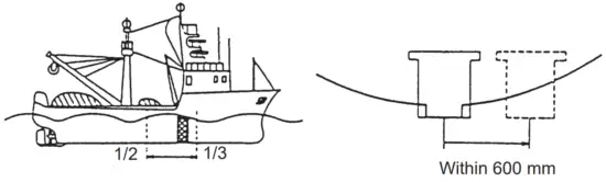
- Select a place where the hull bottom is flat and the draft is sufficiently deep. Normally, the transducer should protrude at least 500 mm beyond the keel to minimize the effect of air foam and bubbles.
- Select a place where interference from other transducers is minimal. The hull unit should be at least 2.5 m away from the transducers of other equipment.
- No obstacle should be in the fore direction since it causes a shadow zone and aeration, resulting in poor sonar performance.
- Select a mounting location, considering the ship’s bottom structure and other sonar equipment. If the ship’s bottom structure and transducer for other sonar equipment is projected more than the FSV-75 transducer, the FSV-75 cannot display sonar echoes correctly. Similarly, if the FSV-75 transducer blocks another sonar transducer, other sonar equipment cannot display the sonar echoes correctly.
- In the case of a bilge keel, select a location as far from the bilge as possible.
- Select a location away from indents and protrusions on the hull, especially indents, as they can create noise interference and cause poor sonar performance.
- Referring to the outline drawings at the back of this manual, allow sufficient space for maintenance and service.
- If the ambient temperature will be below 0°C, provide the sonar compartment with a heater to keep the temperature above 0°C. The hull unit can not work if the ambient temperature is below 0°C.
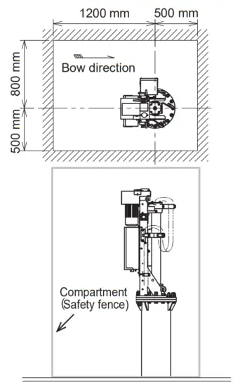
- Prepare a secure and firm safety fence for the hull unit, to prevent accidental injury from the moving hull unit. The safety fence should be easily removable for maintenance and allow room for the connected cables to swing freely with pitch, roll, and heave. The power switch on the control box should be operable from outside the safety fence.
- After you mount the hull unit, be sure to install anti-vibration stays.
1.2.2 Guideline for how to shorten the retraction tank
The recommended tank length for 800 mm and 1100 mm travel hull units is as follows:
- 800 mm travel: 900 mm retraction tank is recommended.
- 1100 mm travel: 1200 mm retraction tank is recommended.
Shorten the tank as necessary so that the transducer positions well below the keel when it is fully lowered. The following table provides guidelines for shortening the tank.
Refer also to the retraction tank installation drawing at the back of this manual.Installation Method
Travel


800 mm
travelCut 0-100 mm from the end. Cut 0-100 mm from the end.
Note that the length “D” must be less than 200 mm.1100 mm
travelCut 0-100 mm from the end. Cut 0-100 mm from the end. Note that the length “D” must be less than 500 mm.
Note 1: Adjust the position for the TX limit switch, according to the retraction tank length. For how to adjust the position for the TX limit switch, see section 1.2.8.
Note 2: When the maximum length is removed and “D” is at a minimum, the effect of aeration is minimized because the transducer fully protrudes in water.
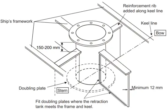
Guideline for the installation of the retraction tank
- If the keel plate on the inside of the hull is not adequate for installing the retraction tank, install a secondary keel plate.
- Install the retraction tank where the keel plate and hull frame intersect.
- If there is no suitable location where the hull frame and keel intersect, install suitable “T” shaped reinforcement ribs, then weld the base of the frame to the reinforcement
ribs and the sides of the reinforcement ribs to the hull walls or other nearby reinforcement ribs. The reinforcement ribs should be secured in the fore, aft, port, and starboard directions. - Install the reinforcement ribs as near as possible to the top of the retraction tank, allowing 150 to 200 mm space for tightening of nuts and bolts.
- Fit a doubling plate (a plate added to another to give extra strength or stiffness) to the location where the retraction tank is welded to the hull bottom. While it is recommended that both sides attach to the hull, consult with the installer regarding length and diameter.
- The thickness for doubling plates and reinforcement ribs is 12 mm minimum.
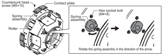
1.2.3 Preparation when an FRP retraction tank (inner diameter: 306 mm) is used
Note: The following procedure is required only when an FRP retraction tank (inner diameter: 306 mm) is used. If a steel retraction tank (inner diameter 316 mm) is used, skip the following procedure.
- Unfasten the six countersunk head screws (M5×10) to remove the contact plate (four locations). Discard the removed contact plates and screws.
- Remove the three hex socket bolts (M4×8) that secure the spring assembly (four locations).
- Rotate the four spring assemblies by 90° in the direction of the arrow on the bottom of the spring assembly, then secure the spring assemblies using the hex socket bolts that were removed at step 2. If you cannot rotate the spring assembly by hand, use a tool such as a wrench whose hex size is 19 mm.
- Check that the four rollers on the side of the tank guide are pushed inwards approx. 5 mm.
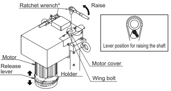
1.2.4 Preparation before installing the hull unit on the retraction tank
An anti-vibration guide is attached to the FSV-75 hull unit shaft. The rollers on the guide can prevent the hull unit from being installed into the retraction tank. For this reason, the rollers must be pushed inwards BEFORE installing the hull unit into the retraction tank.
Note: The following procedure is also required when you remove the hull unit from the retraction tank.
- Unfasten the two wing bolts at the top of the hull unit, then rotate the motor cover.
- Pull the release lever away from the holder.
- Attach the ratchet wrench, referring to the figure at step 6.
- Push the release lever up or down to release the motor brake, keeping a firm hold on the ratchet wrench.
- With the motor brake released, turn the ratchet counter-clockwise to raise the shaft (tank guide).
- While keeping a firm hold on the ratchet wrench, let go of the release lever.
![]() CAUTION
CAUTION![]() Do not release the ratchet wrench before letting go of the release lever. If you let go of the release lever, the ratchet wrench spins freely and may cause serious injury.
Do not release the ratchet wrench before letting go of the release lever. If you let go of the release lever, the ratchet wrench spins freely and may cause serious injury.
*: An extension bar whose length is approx. 40 mm may improve work efficiency.
7. Repeat step 4 to step 6 to raise the shaft (tank guide) until the gap between the tank guide and pedestal is approx. 13 mm (for the steel retraction tank (inner diameter: 316 mm)) or 8 mm (for the FRP retraction tank (inner diameter: 306 mm)). When the shaft is raised, the roller springs are forced downwards by the pedestal, pushing the rollers inwards.
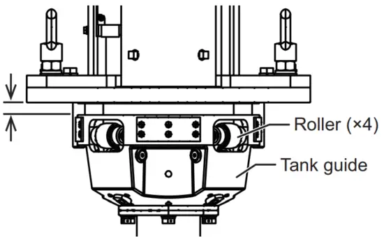
- Steel retraction tank (inner diameter: 316 mm): 13 mm
- FRP retraction tank: (inner diameter: 306 mm): 8 mm
Note: Roller springs reactively push against the shaft, which can add load to the ratchet as the shaft is raised. Keep this in mind when raising the shaft and continue to raise it until the gap between the pedestal and the tank guide is approximately 13 mm (for the steel retraction tank (inner diameter: 316 mm)) or 8 mm (for the FRP retraction tank (inner diameter: 306 mm)).
8. Reattach the release lever to the holder.
9. Replace the ratchet wrench and motor cover.
1.2.5 How to install the hull unit on the retraction tank
Weld the retraction tank and allow sufficient time for cooling. Install the hull unit as follows:
Note: For installation using an existing CSH series hull unit retraction tank, see section 1.10.
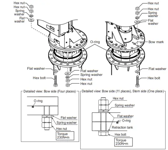
- Clean the flange and O-ring groove of the retraction tank (welded to hull). Use waste cloths moistened with ethyl alcohol.
- Coat the O-ring and O-ring groove with lithium grease, then place the O-ring in its groove on the tank flange.
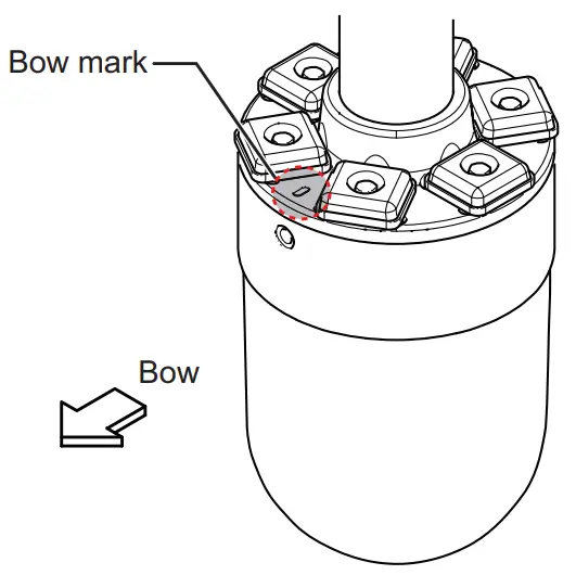
- Orient the hull unit so that the bow mark (inscribed on its flange) points toward the ship’s bow.
Note: If the bow mark on the hull unit flange is not facing the ship’s bow, rotate the transducer so that the bow mark on the transducer points toward the ship’s bow
(see section 1.2.9). - Confirm the following points, then place the hull unit on the retraction tank.
• Clean the flange platform.
• Wipe the undersurface of the hull unit flange with clean waste cloths.
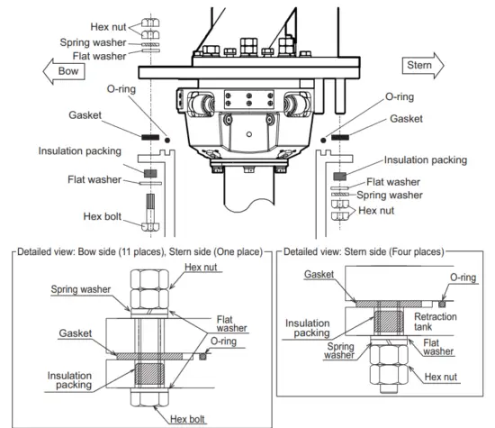
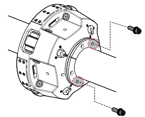
• Keep O-ring in its groove. - Coat the threads of the bolts with a slight amount of lithium grease to prevent scorching, then secure the hull unit to the retraction tank, referring to the following figure.

Lower the transducer, then confirm that the rollers on the tank guide are not projected from the retraction tank. The tank guide must be positioned 30 mm inside from the bottom of the retraction tank.
Note: The position for the lower limit switch can be raised 100 mm by using the bolt holes on the flange assembly.
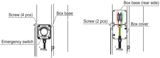
1.2.6 How to remount the emergency switch
The emergency switch is attached to the starboard side of the hull unit. If the starboard side clearance is not sufficient for switch operation, the switch may be remounted on the port side.
- Unfasten the four screws to remove the box base.
- Unfasten the two screws to remove the box cover.

- Remount the emergency switch to the port side.
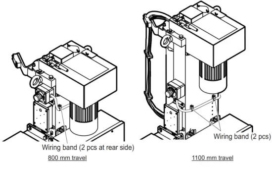
Note: For the 800 mm travel hull unit, rotate the emergency switch by 90° so that the emergency switch cable passes through the rear side of the hull unit (see the figure at step 4). - Secure the emergency switch cable, using the two wiring bands. The wiring band must be secured to the hull unit, using pan head screws (M4×12).

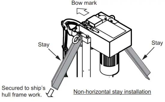
1.2.7 How to install the stays (anti-vibration and anti-shock measures)
This measure must be done after installing the hull unit to prevent damage from vibration or impact shock to the transducer. Stays should be as sturdy as possible (75×75×9 mm minimum recommended). Install a minimum of two stays, one in the aft direction, and one in the fore direction. Where possible install two more stays (one in the port and one in the starboard direction), making a total of four stays. Where the hull unit is installed off-center from the bow-stern line, install the stays at right angles with the bow mark on the hull unit.
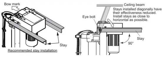
Where horizontal installation of the stays is not possible, install the stays in a diagonal manner to reduce vibration in the hull unit.
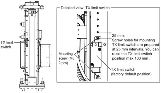
1.2.8 How to adjust the TX limit switch position
Adjust the TX limit switch position so that the switch is turned on where the transmitting face of the transducer is projected from the hull unit.
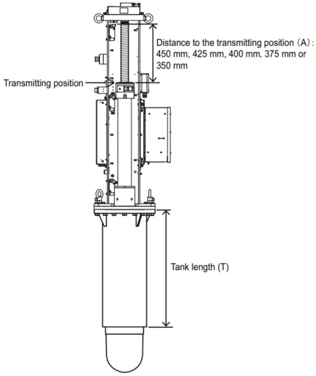
Distance to the transmitting position (A) can be selected from 450 mm, 425 mm, 400 mm, 375 mm, or 350 mm. The distance to the transmitting position can be calculated with the following formula. Select the value closest to the calculation.
- 800 mm travel: A = T- 550 mm
- 1100 mm travel: A = T – 850 mm For example, when the tank length (T) for the 800 mm travel is 920 mm, the calculated value is “ A = 920 – 550 = 370 mm”. Therefore, adjust the TX limit switch so that the distance to the transmitting position is 375 mm.
Note: The transducer can transmit when the transducer is projected 270 mm from the retraction tank.
At factory default, the distance to the transmitting position is 450 mm (tank length: 1000 mm (800 mm travel) or 1300 mm (1100 mm travel)). To adjust the distance to the transmitting position, unfasten the two mounting screws (M6) to remount the TX limit switch.
1.2.9 How to adjust the bow mark directly on the transducer
When you cannot face the bow mark on the hull unit flange to the bow direction due to installation space, rotate the transducer so that the bow mark on the transducer points toward the ship’s bow.
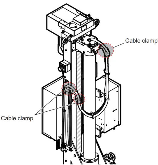
- Release the transducer cable from the three cable clamps.

- Lower the transducer manually.
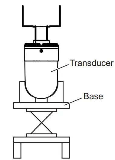
Note: For how to lower the transducer manually, follow the procedure indicated on the label at the top of the hull unit. - Mount the transducer on a base to prevent the transducer from falling accidentally.

- Insert four bolts (M10×80, supplied locally) to the hole on the bottom of the tank guide to push the tank guide rollers inwards.
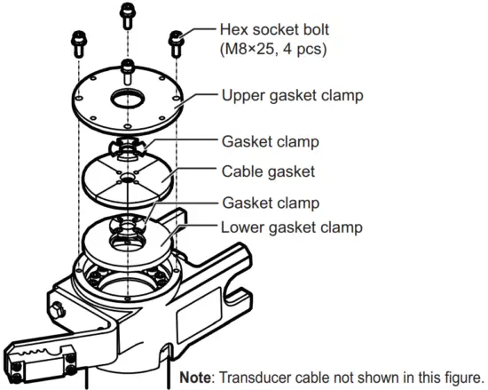
Note: Steel bolts are recommended to prevent scorching. - Unfasten the four hex socket bolts on the top of the main shaft to disassemble the cable gasket assembly.

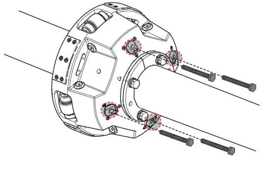
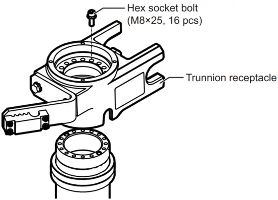
- Unfasten the 16 hex socket bolts to remove the trunnion receptacle from the main shaft.

- Rotate the transducer so that the bow mark on the transducer points toward the ship’s bow.

- Reattach the trunnion receptacle.
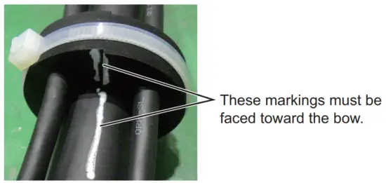
- Assemble the cable gasket on the top of the main shaft.
Note: The following marking appears on the cable gasket and transducer cable. Assemble the cable gasket so that each marking points toward the ship’s bow.
- Remove the four bolts inserted to the tank guide at step 4.
- Raise the transducer manually.
- Secure the transducer cable with the three clamps indicated at step 1.
Note: For how to route the transducer cable, see page 2-3.
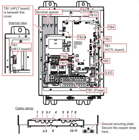
1.2.10 How to check the soundhole assembly operation
After installing the hull unit, check the soundhole assembly operation before wiring.
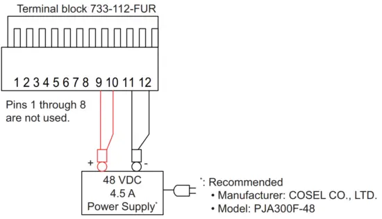
- Prepare a power cable (supplied locally) to supply the power to the soundhole assembly.

- Turn the control box breaker off.
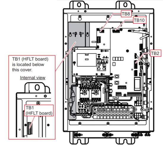
- Open the control box cover, then make connections referring to the following figure.
The operation check can be performed regardless of the settings for connectors other than the ones indicated in this procedure.
Connection with the soundhole assembly
Following connectors must be connected.
The hull unit is supplied with the following connectors connected.
• TB1HFLT board
• TB8
• TB10
Connection with the 48 VDC power supply
• TB2: Connect the power cable prepared at step 1.
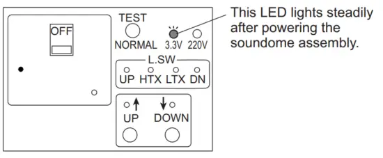
- Turn the 48 VDC power supply on to supply the power to the soundhole assembly, then confirm that the 3.3 V LED on the control box lights steadily.
 When the soundome assembly is powered correctly, an operation check is performed automatically. The decimal point on the display LED flashes during the operation check. The operation check takes approx. one minute.
- After completing the operation check, press the mode select button to change the display mode LED indication to “E”. When the display mode LED shows “E”, when an error is detected, the error code appears on the check result LED. For details about the error codes, see “Error code” on page 1-17.
Note: If errors are detected during the operation check, the check result LED shows the error code automatically. - Turn the 48 VDC power supply off and disconnect the power cable from TB2.
- Reattach the control box cover.
 When the soundome assembly is powered correctly, an operation check is performed automatically. The decimal point on the display LED flashes during the operation check. The operation check takes approx. one minute.
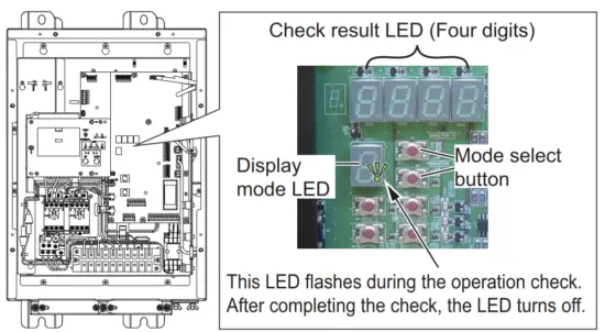
Error code
Error codes appear on the check result LED as alphanumeric characters.
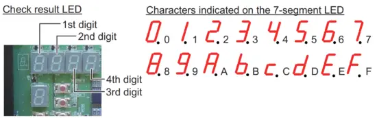
Use the following four tables to confirm the error code. For example, when the error code is “0A00”, “6 HCTL Power Error” and “8 hull unit Operation Error” occur. For error details, see the table on the following page.
- Error that can be indicated by the 1st digit LED:
| Error | Character on the seven-segment LED ✓: Error occurs. | ||||||||||||||||
| 0 | 1 | 2 | 3 | 4 | 5 | 6 | 7 | 8 | 9 | A | B | C | D | E | F | ||
| 1 | Motion Sensor Connection Error or Motion Sensor ROM/RAM Error | – | ✓ | – | ✓ | – | ✓ | – | ✓ | – | ✓ | – | ✓ | – | ✓ | – | ✓ |
| 2 | Motion Sensor Self Test Error | – | – | ✓ | ✓ | – | – | ✓ | ✓ | – | – | ✓ | ✓ | – | – | ✓ | ✓ |
| 3 | Motion Sensor Power Error | – | – | – | – | ✓ | ✓ | ✓ | ✓ | – | – | – | – | ✓ | ✓ | ✓ | ✓ |
| 4 | Motion Sensor Calibration Error | – | – | – | – | – | – | – | – | ✓ | ✓ | ✓ | ✓ | ✓ | ✓ | ✓ | ✓ |
- Error that can be indicated by the 2nd digit LED:
| Error | Character on the seven-segment LED ✓: Error occurs. | ||||||||||||||||
| 0 | 1 | 2 | 3 | 4 | 5 | 6 | 7 | 8 | 9 | A | B | C | D | E | F | ||
| 5 | Resolver Driver Error (T It) | – | ✓ | – | ✓ | – | ✓ | – | ✓ | – | ✓ | – | ✓ | – | ✓ | – | ✓ |
| 6 | HCTL Power Error | – | – | ✓ | ✓ | – | – | ✓ | ✓ | – | – | ✓ | ✓ | – | – | ✓ | ✓ |
| 7 | Fan Rotation Error | – | – | – | – | ✓ | ✓ | ✓ | ✓ | – | – | – | – | ✓ | ✓ | ✓ | ✓ |
| 8 | Hull Unit Operation Error | – | – | – | – | – | – | – | – | ✓ | ✓ | ✓ | ✓ | ✓ | ✓ | ✓ | ✓ |
- Error that can be indicated by the 3rd digit LED:
| Error | Character on the seven-segment LED ✓: Error occurs. | ||||||||||||||||
| 0 | 1 | 2 | 3 | 4 | 5 | 6 | 7 | 8 | 9 | A | B | C | D | E | F | ||
| 9 | Motor Test Error (Tilt) | – | ✓ | – | ✓ | – | ✓ | – | ✓ | – | ✓ | – | ✓ | – | ✓ | – | ✓ |
| 10 | Motor Driver Error (Rotate) | – | – | ✓ | ✓ | – | – | ✓ | ✓ | – | – | ✓ | ✓ | – | – | ✓ | ✓ |
| 11 | Motor Driver Error (Tilt) | – | – | – | – | ✓ | ✓ | ✓ | ✓ | – | – | – | – | ✓ | ✓ | ✓ | ✓ |
| 12 | Resolver Driver Error (Rotate) | – | – | – | – | – | – | – | – | ✓ | ✓ | ✓ | ✓ | ||||
- Error that can be indicated by the 4th digit LED:
| Error | Character on the seven-segment LED ✓: Error occurs. | ||||||||||||||||
| 0 | 1 | 2 | 3 | 4 | 5 | 6 | 7 | 8 | 9 | A | B | C | D | E | F | ||
| 13 | HCTL ROM/RAM Error | _ | ✓ | _ | ✓ | _ | ✓ | _ | ✓ | _ | ✓ | _ | ✓ | _ | ✓ | – | ✓ |
| 14 | Resolver Test Error (Rotate) | _ | _ | ✓ | ✓ | _ | _ | ✓ | ✓ | _ | _ | ✓ | ✓ | _ | _ | ✓ | ✓ |
| 15 | Resolver Test Error (Tilt) | _ | _ | _ | _ | ✓ | ✓ | ✓ | ✓ | _ | _ | _ | _ | ✓ | ✓ | ✓ | ✓ |
| 16 | Motor Test Error (Rotate) | _ | _ | _ | _ | _ | _ | _ | _ | ✓ | ✓ | ✓ | ✓ | ✓ | ✓ | ✓ | ✓ |
The following table provides detailed information for each error.
| Error | Meaning | Possible reason(s) | |
| 1 | Motion Sensor Connection Error or Motion Sensor ROM/RAM Er- ror | There is a problem communicating with the motion sensor, or a motion sensor error was detected at startup. |
|
| 2 | Motion Sensor Self Test Error | Motion sensor self-test de- tests one or more errors. | HMS board error |
| 3 | Motion Sensor Power Error | Motion sensor self-test de- tests one or more errors. | HMS board error |
| 4 | Motion Sensor Calibration Error | Motion sensor calibration test detects one or more errors. | HMS board error |
| 5 | Resolver Driver Error (Tilt) | Resolver driver self-test de- tests one or more errors. | HCTL board error |
| 6 | HCTL Power Error | Power error for the HCTL board (24 V, 12 V, 5V). | HCTL board error |
| 7 | Fan Rotation Error | Fan rotation speed is slow. |
|
| 8 | Hull Unit Operation Er- ror | Hull unit malfunction. |
|
| Error | Meaning | Possible reason(s) | |
| 9 | Motor Test Error (Tilt) | Tilt motor self-test detects one or more errors. |
Note: Perform a disconnection and short circuit check for the motor cable. |
| 10 | Motor Driver Error (Rotate) | Motor driver IC is overheated, or overcurrent is detected. |
Note: Perform a disconnection and short circuit check for the motor cable. |
| 11 | Motor Driver Error (Tilt) | ||
| 12 | Resolver Driver Error (Rotate) | Resolver driver self-test de- tests one or more errors. | HCTL board error |
| 13 | HCTL ROM/RAM Error | HCTL board self-test at CPU startup detects one or more errors. | HCTL board error |
| 14 | Resolver Test Error (Rotate) | Resolver test detects one or more errors. |
Note: Perform a disconnection and short circuit check for the resolver. |
| 15 | Resolver Test Error (Tilt) | ||
| 16 | Motor Test Error (Rotate)* | Rotation motor self-test detects one or more errors. |
Note: Perform a disconnection and short circuit check for the motor cable. |
*: When the resolver has one or more errors, motor test shows error. Therefore, rectify the resolver error before rectifying the motor test error.
- When “5 Resolver Driver Error (Tilt)” or “15 Resolver Test Error (Tilt)” is detected, “9 Motor Test Error (Tilt)” occurs.
- When “12 Resolver Driver Error (Rotate)” or “14 Resolver Test Error (Rotate)” is detected, “16 Motor Test Error (Rotate)” occurs.
Disconnection/short circuit check
When one or more of the following errors occur, perform a disconnection/short circuit check for the resolver or motor.
| Occurred error | Check point |
| 9 Motor Test Error (Tilt) | Perform a disconnection/short circuit check for the motor. |
| 10 Motor Driver Error (Rotate) | |
| 11 Motor Driver Error (Tilt) | |
| 16 Motor Test Error (Rotate) | |
| 14 Resolver Test Error (Rotate) | Perform a disconnection/short circuit check for the re-solver. |
| 15 Resolver Test Error (Tilt) |
- Disconnection/short circuit check for the motor Remove the terminal block 734-209-FUR from the TB1 (HFLT board) in the control box, then measure resistance using a multimeter.
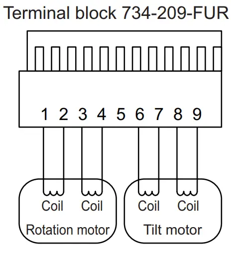
| Measured point | Correct value | If the measured value is not the correct value… |
| 1-2, 3-4 | 10 to 30 Ω | Rotation motor or motor cable error |
| 6-7, 8-9 | 10 to 30 Ω | Tilt motor or motor cable error |
| 1-3 | ∞ | Insulation failure in the rotation motor or motor cable. |
| 6-8 | ∞ | Insulation failure in the tilt motor or motor cable. |
| Between ground point (hull unit chassis) and pins 1 thru 4, 6 thru 9 | ∞ | Insulation failure in the motor or motor cable. |
- Disconnection/short circuit check for the resolver Remove the terminal block 733-106-FUR and 733-110-FUR from the TB8 and TB10 in the control box, then measure resistance using a multimeter.
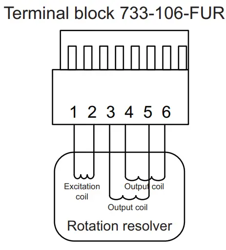
| Measured point | Correct value | If the measured value is not correct value… |
| 1-2 | 50 to 70Ω | Rotation resolver or resolver cable error When the extension box is used: Insulation failure in the extension box |
| 3-5, 4-6 | 100 to 130Ω | |
| 3-4 | ∞ | |
| Between ground point (hull unit chassis) and pins 1 thru 6 | ∞ |
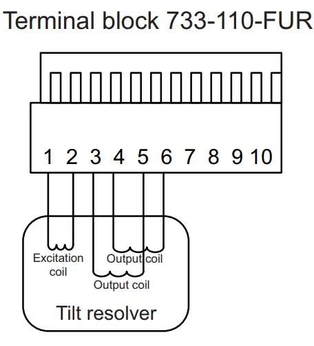
| Measured point | Correct value | If the measured value is not correct value… |
| 1-2 | 50 to 70 Ω | Tilt resolver or resolver cable error When the extension box is used: Insulation failure in the extension box |
| 3-5, 4-6 | 100 to 130 Ω | |
| 3-4 | ∞ | |
| Between ground point (hull unit chassis) and pins 1 thru 6 | ∞ |
1.3 Processor Unit
The processor unit can be installed on a deck or bulkhead.
Mounting considerations
Select a mounting location, keeping in mind the following points:
- Locate the unit out of direct sunlight and away from heat sources.
- Locate the unit away from places subject to water splash and rain.
- Select a mounting location considering the length of the cables to be connected to the unit.
- Select a location where shock and vibration are minimal.
- Be sure the mounting location is strong enough to support the weight of the unit.
- Referring to the outline drawings at the back of this manual, allow sufficient space for maintenance and service.
- A magnetic compass will be affected if the unit is placed too close to the magnetic compass. Observe the compass safe distances at the front of this manual to prevent
interference to a magnetic compass. - For the bulkhead installations, secure the unit so that the cable entrance faces downward.
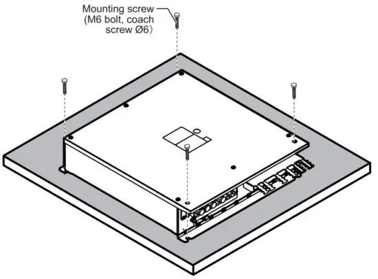
1.3.1 Deck mount
- Drill four pilot holes in the mounting location for mounting screws (M6 bolts or coach screws Φ6), referring to the outline drawing at the back of this manual.
- Secure the unit using the four mounting screws (supplied locally).
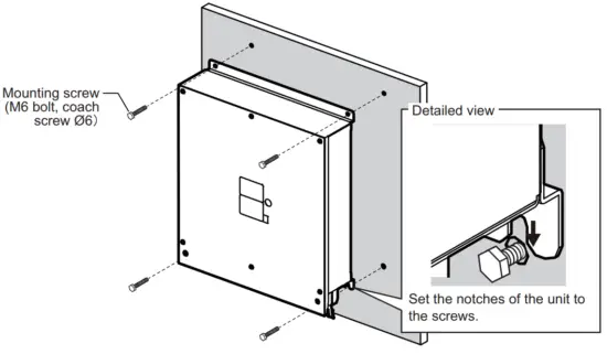
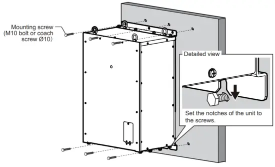
1.3.2 Bulkhead mount
- Drill four pilot holes in the mounting location for mounting screws (M6 bolts or coach screws Φ6), referring to the outline drawing at the back of this manual.
- Screw two mounting screws (supplied locally) into the lower pilot holes. Leave 5mm of thread visible.
- Set the notches of the unit onto the screws fastened at step 2.
- Screw two mounting screws (supplied locally) into the upper fixing holes.
- Fasten all screws tightly to secure the unit in place.
1.4 Control Unit
The control unit has the following three mounting methods:
- Tabletop mounting: The unit is secured from the underside.
- Tabletop mounting with KB fixture: The unit is secured from the topside.
- Flush mounting
Mounting considerations
- Select a location where the unit can easily be operated.
- Locate the unit out of direct sunlight.
- Locate the unit away from places subject to water splash and rain.
- Select a location where shock and vibration are minimal.
- Select a mounting location considering the length of the cable.
- Referring to the outline drawings at the back of this manual, allow sufficient space for maintenance and service.
- A magnetic compass will be affected if the unit is placed too close to the magnetic compass. Observe the compass safe distances at the front of this manual to prevent
interference with a magnetic compass. - For flush installations, select a location where the surface is flat.
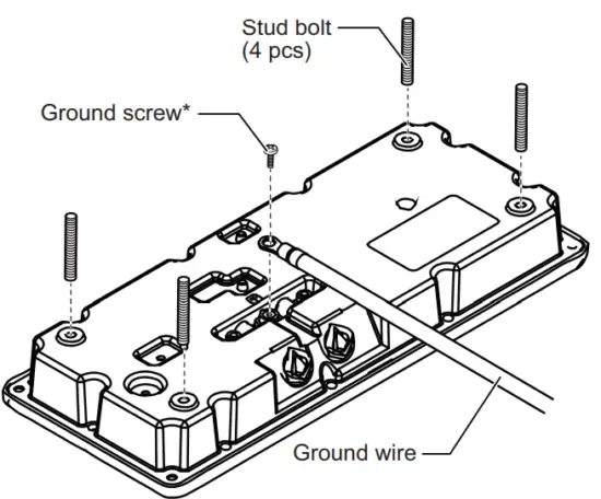
1.4.1 Tabletop mounting without KB fixture
- Drill four pilot holes in the mounting location for stud bolts (M4×50), referring to the outline drawing at the back of this manual.
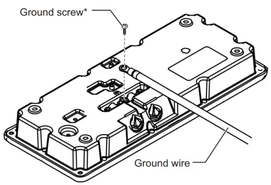
- Attach a ground wire (IV-1.25sq, supplied locally) to the ground terminal at the bottom of the unit, then connect the other end of the ground wire with the ship’s ground.
- Insert four stud bolts (M4×20, supplied) to the bolt holes at the bottom of the unit.
Note: Insert the stud bolts manually. Do not use a tool to insert the bolts – the unit may become damaged. *: Use the screw that is preattached to the ground terminal.
 - Set the unit to the mounting location so that the stud bolts on the bottom of the unit are inserted to the pilot holes.
Note: Be careful to prevent the ground wire from being caught between the unit chassis and the mounting surface. - Fasten the four wing nuts (supplied) to the stud bolts from the rear side of the mounting surface.

 *: Use the screw that is preattached to the ground terminal.
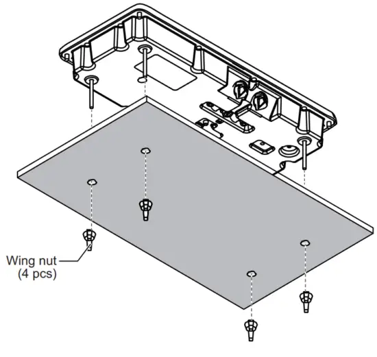
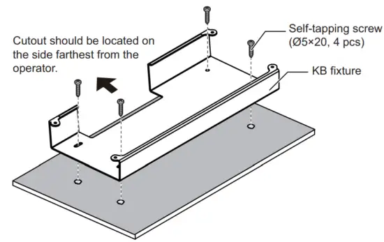
1.4.2 Tabletop mounting with KB fixture
The control unit can be mounted with the KB fixture, which mounts the unit at an angle.
- Drill four pilot holes in the mounting location for mounting screws, referring to the outline drawing at the back of this manual.
- Secure the KB fixture (supplied) to the mounting location, using four self-tapping screws (Φ5×20, supplied).
Note: Secure the KB fixture so that the cutout is located on the side farthest from the operator.
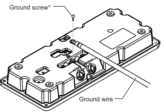
- Attach a ground wire (IV-1.25sq, supplied locally) to the ground terminal at the bottom of the unit, then connect the other end of the ground wire with the ship’s ground.
 *: Use the screw that is preattached to the ground terminal.
 - Secure the control unit the KB fixture, using four binding screws (M5×20, supplied).
- Attach four bolt hole caps (supplied).

 *: Use the screw that is preattached to the ground terminal.
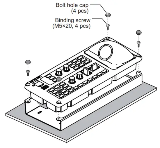
1.4.3 Flush mounting
Note: Be sure the mounting surface is flat.
- Referring to the outline drawing at the back of this manual, prepare a cutout, then drill four pilot holes in the mounting location.
- Attach a ground wire (IV-1.25sq, supplied locally) to the ground terminal at the bottom of the unit, then connect the other end of the ground wire with the ship’s ground.
 *: Use the screw that is preattached to the ground terminal.
 - Set the unit to the cutout, then secure the unit with four self-tapping screws (Φ5×20, supplied).
- Attach four bolt hole caps (supplied).

 *: Use the screw that is preattached to the ground terminal.
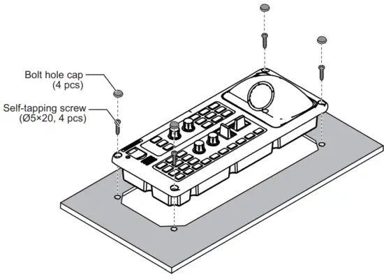
1.5 Transceiver Unit
The transceiver unit can be installed on a deck or bulkhead.
Mounting considerations
Select a mounting location, keeping in mind the following points:
- Locate the unit out of direct sunlight and away from heat sources.
- Locate the unit away from places subject to water splash and rain.
- Select a mounting location considering the length of the cables to be connected to the unit.
- Select a location where shock and vibration are minimal. Reinforce the transceiver unit against vibration by stays extending from the eyebolts on the top of the unit, as
needed. - Be sure the mounting location is strong enough to support the weight of the unit.
- Referring to the outline drawings at the back of this manual, allow sufficient space for maintenance and service.
- A magnetic compass will be affected if the unit is placed too close to the magnetic compass. Observe the compass safe distances at the front of this manual to prevent interference with a magnetic compass.
- For installation on a deck, use the bolt holes on the top and bottom of the unit. If the three bolt holes on the top of the unit are not used, or the mounting direction is not followed as shown in the following figure, the quality and performance may be reduced.
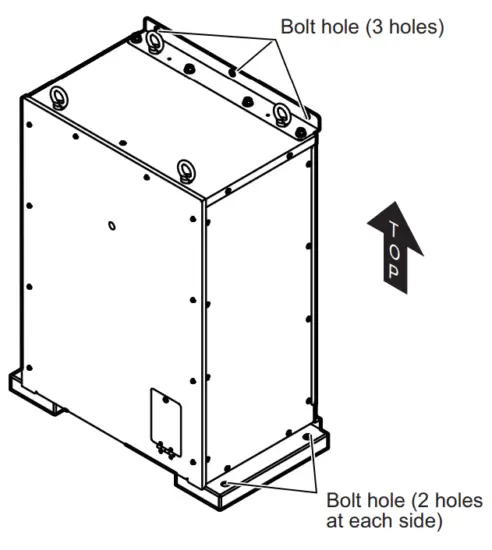
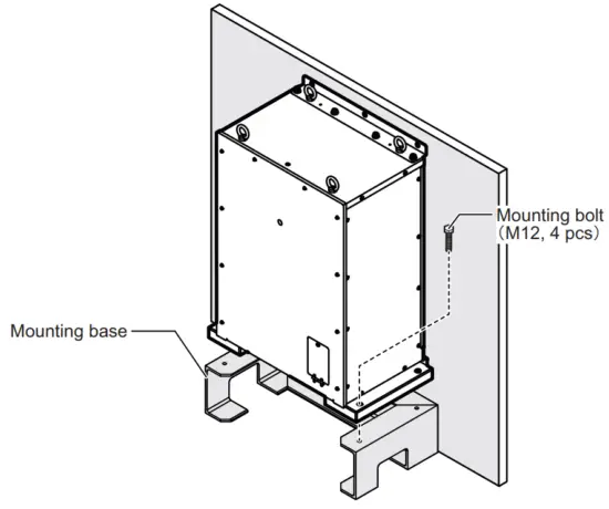
1.5.1 Deck mounting
- Have the shipyard manufacture and fit a mounting base (SS400) at the mounting location.
- Secure the unit to the mounting base, using four mounting bolts (M12, supplied locally).

- Insert three mounting screws (M10 bolts or coach screw Φ10, supplied locally) to the bolt holes on the top of the unit.
 Note: Be sure to use the bolt holes on the top of the unit. When the back of the unit is not in contact with a bulkhead, prepare a stay or mounting base, referring to the following example.
 Note: Be sure to use the bolt holes on the top of the unit. When the back of the unit is not in contact with a bulkhead, prepare a stay or mounting base, referring to the following example.
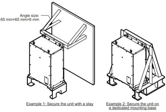
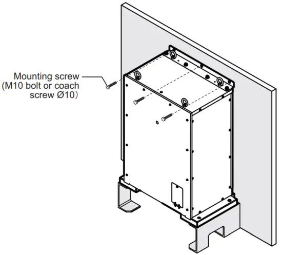
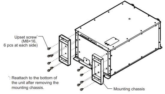
1.5.2 Bulkhead mounting
- Remove the two mounting chassis on the bottom of the unit.
Note: Reattach upset screws to the bottom of the unit after removing the mounting chassis. - Drill six pilot holes in the mounting location for mounting screws (M10 bolts or coach screws Φ10), referring to the outline drawing at the back of this manual.
- Screw three mounting screws (supplied locally) into the lower pilot holes. Leave 5 mm of thread visible.
- Set the notches of the unit onto the screws fastened at step 3.
- Screw three mounting screws (supplied locally) into the upper fixing holes.
- Fasten all screws tightly to secure the unit in place.

1.6 Matching Box
Install the matching box on the hull unit. The following two mounting directions are available for the matching box.
- The matching box cover faces to the port side.
- Matching box cover faces in the stern direction. This mounting direction is the same as the control box.
Note: If the matching box is to be installed facing in the stern direction, change the mounting base positions.
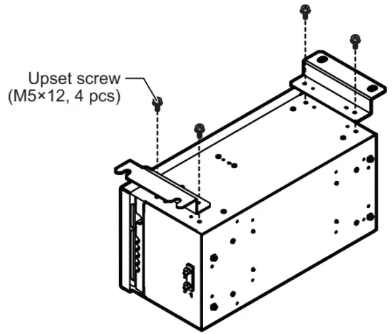
Matching box cover facing to port
- Screw two mounting screws (M10, supplied) into the lower fixing holes on the hull unit. Leave 5 mm of thread visible.
- Set the notches of the unit onto the screws fastened at step 1.
- Screw two mounting screws (M10, supplied) into the upper fixing holes.
- Fasten all screws tightly to secure the unit in place.

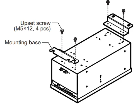
Matching box cover facing to stern
- Unfasten the four upset screws (M5×12) to remove the two mounting bases from the bottom of the unit.

- Remove the four binding screws (M5×12) from the right side of the unit, then insert the screws into the screw holes for the upset screws that were removed in step 1.
- Attach the two mounting bases to the right side of the unit, using the upset screws that were removed at step 1.

- Screw the two mounting screws (M10, supplied) into the lower fixing holes on the hull unit. Leave 5 mm of thread visible.
- Set the notches of the unit onto the screws fastened at step 4.
- Screw the two mounting screws (M10, supplied) into the upper fixing holes.
- Fasten all screws tightly to secure the unit in place.

1.7 Control Box
The control box is preattached to the hull unit. When mounting the control box separately from the hull unit, use the optional extension box. The control box must be installed on a bulkhead.
Mounting considerations
Select a mounting location, keeping in mind the following points:
- Locate the unit out of direct sunlight and away from heat sources.
- Locate the unit away from places subject to water splash and rain.
- Select a mounting location considering the length of the cables to be connected to
the unit. - Select a location where shock and vibration are minimal.
- Be sure the mounting location is strong enough to support the weight of the unit.
- Referring to the outline drawings at the back of this manual, allow sufficient space for maintenance and service.
- A magnetic compass will be affected if the unit is placed too close to the magnetic compass. Observe the compass safe distances at the front of this manual to prevent interference with a magnetic compass.
- Secure the unit so that the cable entrance faces downward.
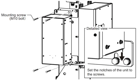
When mounting the control box separately from the hull unit
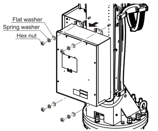
- Unfasten the four hex nuts, spring washers, and flat washers to remove the control box from the hull unit.
Note: The removed hex nuts, spring washers, and flat washers are re-used when mounting the extension box to the hull unit.
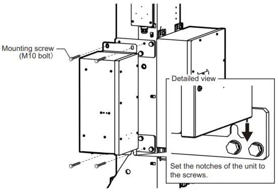
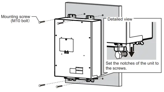
- Drill four pilot holes in the mounting location for mounting screws (M10 bolt), referring to the outline drawing at the back of this manual.
- Screw two mounting screws (supplied locally) into the lower pilot holes. Leave 5 mm of thread visible.
- Set the notches of the unit onto the screws fastened at step 3.
- Screw two mounting screws (supplied locally) into the upper fixing holes.
- Fasten all screws tightly to secure the unit in place.

1.8 Extension Box
Install the extension box to the hull unit when mounting the control box separately from the hull unit. Remove the control box from the hull unit, then secure the extension box
to the position where the control box was secured. For how to remove the control box from the hull unit, see section 1.7.
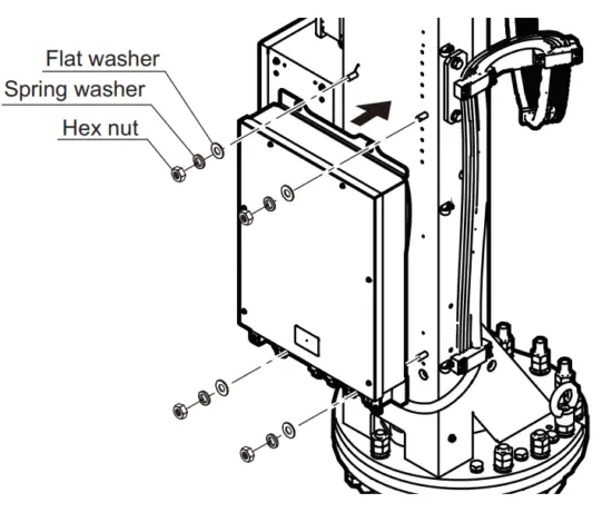
- Set the extension box to the bolt on the rear (stern) side of the hull unit.
- Secure the extension box to the hull unit, using four hex nuts, spring washers, and flat washers.
Note: Use the hex nuts, spring washers, and flat washers that were used for securing the control box.
1.9 How to Fill the Dome with Sonar Oil
Fill the dome with sonar oil as shown below.
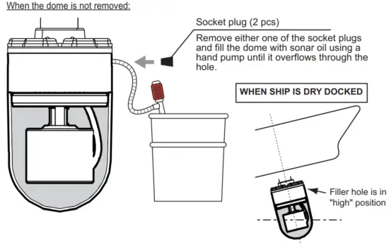
How to attach the socket plug
- Remove the thread sealing tape from the socket plug.
- Starting at the second thread, re-wrap three layers of sealing tape around the threads.
- Pinch the threads between your thumb and a finger to fit the tape with the threads.
- Reattach the socket plug.
Note: The sealing tape is not re-usable after your remove the socket plug. Always re-apply sealing tape after removing a socket plug.
![]()
When the dome is removed:
Fill the dome with sonar oil until the oil reaches the position indicated in the figure to the right.
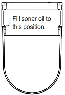
Note 1: When the ship is dry-docked, drain antifreeze from the dome when the temperature is lower than -20°C. Failure to do so can damage the dome.
Note 2: After filling the sonar oil, record the date that you filled sonar oil, referring to section 3.16.
Note 3: If sonar oil comes into contact with the dome surface, clean the dome with a surfactant. Sonar oil can adversely affect the acoustic capabilities of the dome if left on the surface.
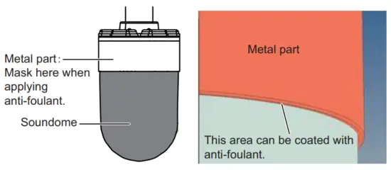
Note 4: When the dome is painted to keep marine life off the transducer, observe the following precautions.
- Use only anti-foulant “SEATENDER20” or SEA GRANDPRIX 660 HS (Manufacture: Chugoku Marine Paint Co. Ltd., Japan).
- Mask the metal part to prevent contact with anti-foulant. However, the underside of the metal part can be painted with anti-foulant.
1.10 Installing to an Existing Retraction Tank
To install the hull unit to the existing retraction tank for the CSH series, use the optional attachment kit or attachment flange.
- When tank length does not need to be extended, use the attachment kit.
- When tank length needs to be extended, use the attachment flange.
1.10.1 When tank extension is not required
When the tank length does not need to be extended for installation to the existing retraction tank, use the optional attachment kit (type: OP10-56).
The items included in the attachment kit are listed in the following table.
| Name | Type | Code No. | Qty | Remarks |
| Gasket | SHG-0003-1 | 100-038-571-10 | 1 | |
| 0-ring | CO 0117A (P355) | 000-158-976-10 | 1 | |
| Insulation Packing | MS-1000-68-1 | 100-347-611-10 | 16 | |
| Stainless Steel Wire | TSW-12 *1M* | 000-179-538-10 | 1 | Used to adjust the tank guide position (see section 1.10.3). |
Note: Remove marine life (barnacles, etc.) from the existing retraction tank before installing the hull unit.
- Clean the flange and O-ring groove of the retraction tank (welded to hull). Use waste cloths moistened with ethyl alcohol.
- Coat the O-ring and O-ring groove with lithium grease, then place the O-ring in its groove on the tank flange.
- Lay the gasket on the top of the tank flange.
- Orient the hull unit so that the bow mark (inscribed) on its flange points toward the
ship’s bow.
Note: If the bow mark on the hull unit flange is not facing the ship’s bow, rotate the transducer so that the bow mark on the transducer points toward the ship’s bow (see section 1.2.9). - Confirm the following points and place the hull unit on the tank.
• Clean the flange platform.
• Wipe the undersurface of the hull unit flange with clean waste cloths.
• Keep the O-ring in its groove.
• Place the hull unit so that the rollers on the tank guide do not contact the weld bead on the retraction tank. If the rollers contact the weld bead, adjust the tank guide position (see section 1.10.3). - Coat the threads of the bolts with a slight amount of lithium grease to prevent scorching, then secure the hull unit to the retraction tank, referring to the following figure.

- Lower the transducer, then confirm that the rollers on the tank guide are not projecting from the retraction tank. Tank guide must be positioned 30 mm inside from the bottom of the retraction tank.
Note: The position for the lower limit switch can be raised 100 mm by using the bolt holes on the flange assembly.
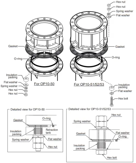
1.10.2 When tank extension is required
If you need to extend the tank length when installing to an existing retraction tank, use the optional attachment flange. Select the correct attachment flange from the following
table, using the length of the pre-installed tank to determine the raising height.
| Name | Type | Raising height |
| Attachment Flange | OP10-50 | 150 mm |
| OP10-51 | 250 mm | |
| OP10-52 | 350 mm | |
| OP10-53 | 450 mm |
Note: Do not use multiple attachment flanges to a retraction tank.
The items supplied with the attachment flange are listed in the following table.
| Name | Type | Code No. | Qty | Remarks |
| Attachment Flange | 10-090-5552 | 100-424-770-10 | 1 | For OP10-50 |
| 10-090-5554 | 100-424-780-10 | For OP10-51 | ||
| 10-090-5555 | 100-424-790-10 | For OP10-52 | ||
| 10-090-5556 | 100-424-800-10 | For OP10-53 | ||
| 0-ring | CO 0117A (P355) | 000-158-976-10 | 1 | |
| Hex Bolt | M20x120 SUS304 | 000-162-825-10 | 16 | Not included for OP10-50. |
| Gasket | SHG-0003-1 | 100-038-571-10 | 1 | |
| Insulation Packing | MS-1000-68-1 | 100-347-611-10 | 16 | |
| Spring Washer | M20 SUS304 | 000-167-401-10 | 16 | |
| Flat Washer | M20 SUS304 | 000-167-452-10 | 32* | |
| Hex Nut | M20 SUS304 | 000-167-476-10 | 32 | |
| Stainless Steel Wire | TSW-12 *1M* | 000-179-538-10 | 1 | Used to adjust the tank guide position (see section 1.10.3). |
*: 16 flat washers are included with OP10-50.
Note: Remove marine life (barnacles, etc.) from the existing retraction tank before installing the hull unit.
- Clean the flange and O-ring groove of the retraction tank (welded to hull). Use waste cloths moistened with ethyl alcohol.
- Coat the O-ring and O-ring groove with lithium grease, then place the O-ring in its groove on the tank flange.
- Lay the gasket on the top of the tank flange.
- Confirm the following points and place the attachment flange on the tank.
• Clean the flange platform.
• Wipe the undersurface of the attachment flange with clean waste cloths.
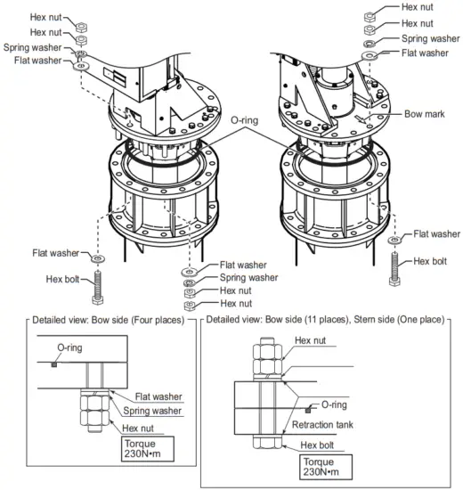
• Keep the O-ring in its groove. - Coat the threads of the bolts with a slight amount of lithium grease to prevent scorching, then secure the attachment flange to the retraction tank, referring to the following figure.

- Orient the hull unit so that the bow mark (inscribed) on its flange points toward the ship’s bow.
Note: If the bow mark on the hull unit flange is not facing the ship’s bow, rotate the transducer so that the bow mark on the transducer points toward the ship’s bow (see section 1.2.9). - Place the hull unit on the attachment flange (retraction tank).
Note: Place the hull unit so that the rollers on the tank guide do not come into contact with the weld bead on the retraction tank. If the rollers contact the weld bead, adjust the tank guide position (see section 1.10.3). - Coat threads of the bolts with a slight amount of lithium grease to prevent scorching, then secure the hull unit to the retraction tank, referring to the following figure.

- Lower the transducer, then confirm that the rollers on the tank guide are not projecting from the retraction tank. Tank guide must be positioned 30 mm inside from the bottom of the retraction tank.
Note: The position for the lower limit switch can be raised 100 mm by using the bolt holes on the flange assembly.
1.10.3 Adjusting the tank guide position
If the rollers on the tank guide come into contact with the weld bead on the retraction tank, rotate the tank guide to adjust the position of the rollers.
- Lower the transducer manually.
Note: For how to lower the transducer manually, follow the procedure indicated on the label at the top of the hull unit. - Insert four bolts (M10×80, supplied locally) in the holes on the bottom of the tank guide to push the tank guide rollers inwards.
Note: Steel bolts are recommended to prevent scorching.
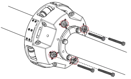
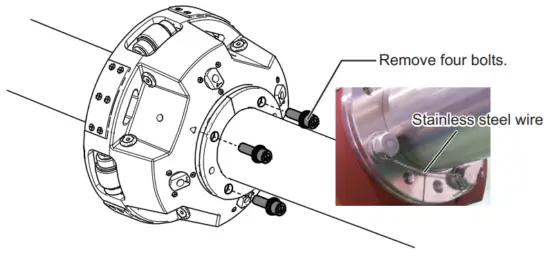
- Remove the four bolts on the bottom of the tank guide and the connected stainless steel wires.

- Insert two of the bolts removed at step 3 in the locations indicated in the figure below, to raise the tank guide. Raise the tank guide until it can be rotated.

- Rotate the tank guide until the rollers on the tank guide do not come into contact with the weld bead on the retraction tank.
- Remove the two bolts inserted at step 4
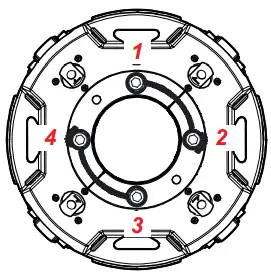
- Reinsert the four bolts removed at step 3 and attach stainless wires* as shown below.
*: Use the stainless steel wire included in the attachment flange or attachment kit. Attach the stainless wire between bolts 1 and 2, 3 and 4. Start at bolts 1 and 3.
- Remove the four bolts inserted at step 2.
- Raise the transducer.
This page is intentionally left blank.
 Attach the stainless wire between bolts 1 and 2, 3 and 4. Start at bolts 1 and 3.
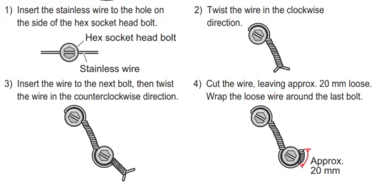
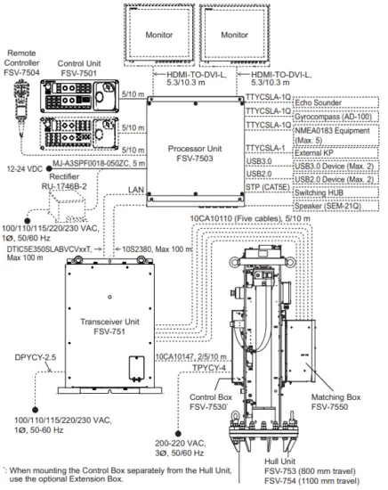
WIRING
The illustration on this page shows the general connection of the FSV-75. For detailed information, see the interconnection diagram. Many of the cables mentioned are JIS (Japanese Industrial Standards) cables. If not available locally, use the equivalent. See the cable guide in the Appendix for how to select equivalent cables.
Notes for network construction
- The transceiver unit must be directly connected to the processor unit. Do not use a network hub for this Ethernet connection.
- When you need 10 m or more cable for the control unit and monitor unit, prepare a commercial adapter.
- For configurations with two monitor units, make sure the resolution is the same for both monitors. Both monitors must also be landscape-oriented. The FSV-75 cannot display images correctly if the monitors do not meet these requirements.
- Do not cut the HDMI cable between the monitor unit and processor unit.
- If the cable between the monitor unit and processor unit is disconnected and reconnected while the system is powered, the FSV-75 may display images incorrectly. Restart the system if this occurs.
- For a configuration with either the MU-190 or MU-190-HD monitor units, monitor brilliance can be adjusted from the control unit. To use this feature, connect a USB cable between the monitor unit and the processor unit. The USB cable must be connected directly between the units; do not use a USB hub.
- For configurations with dual monitors, connect the main monitor to the HDMI1 port and the sub monitor to the HDMI2 port.
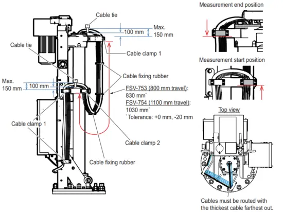
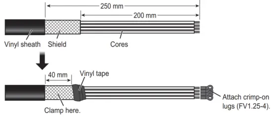
Transducer cable
If the transducer is removed from the hull unit while installing the hull unit, reattach the transducer and route the transducer cables as shown in the following figure.
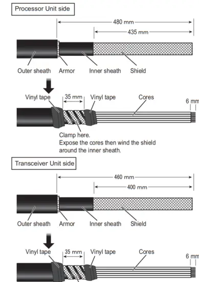
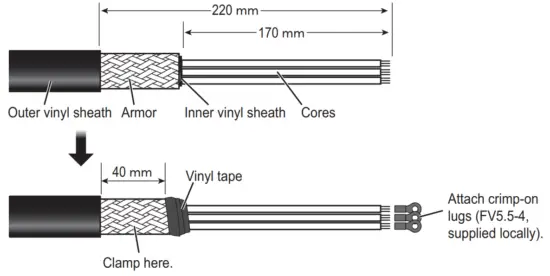
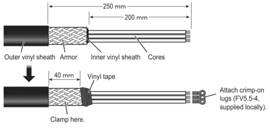
NOTICE
Route the cables so their lengths are as indicated in the figure below.
Failure to observe the lengths may damage or sever cables.
2.1 Processor Unit
2.1.1 Connectors
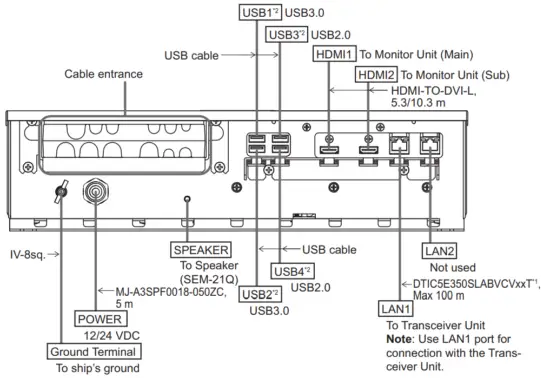
*¹: Fabricate the cable referring to section 2.1.3.
*²: To connect a USB device, use the lower USB port first.
Secure the USB, HDMI, and LAN cables to the cable clamp with a cable tie (supplied locally). For the USB cables, use two cable ties to secure the cable.
Note: The cable clamp can be adjusted to allow larger connectors, such as USB or HDMI, to be connected.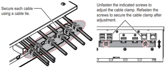 2.1.2 Internal wiring and cable clamp position
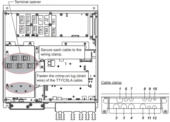
| Clamp position | Connect to | Cable from | Cable |
| / | TB3 | NMEA0183 equipment | TTYCSLA-1Q*1 |
| 2 | TB4 | ||
| 3 | TB5 | ||
| 4 | TB6 | ||
| 5 | TB7 | ||
| 6 | TB10 | Transceiver unit | 10S2380*1 |
| 7 | TB2 | Gyrocompass (AD-10) | TTYCSLA-1Q*1 |
| 8 | J1 | Control unit | – |
| 9 | J2 | Control unit | – |
| 10 | TB1 | Remote controller, external switch*2 | – |
| 11 | TB8 | External KP*3 | TTYCSLA-1*1 |
| 12 | TB9 | External echo sounder | TTYCSLA-1Q*1 |
*¹: Fabricate the cables referring to section 2.1.3.
*²: To connect an external switch, see section 2.1.5.
*³: To connect an external KP, see section 2.1.6.
2.1.3 Cable fabrication
10S2380 cable
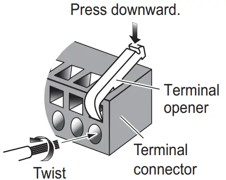
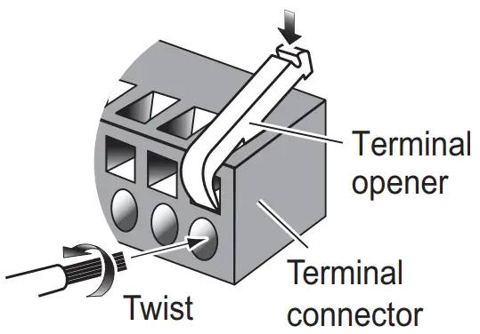
How to connect wires to a terminal connector
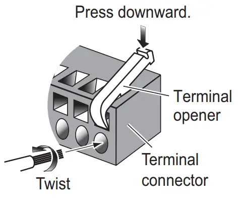
Procedure
- Twist the cores.
- Press the terminal opener downward.
- Insert the wire in the hole.
- Remove the terminal opener.
- Pull the wire to confirm that it is secure.
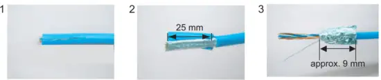
LAN cable
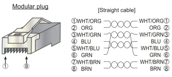
Fabricate the LAN cable (DTIC5E350SLABVCVxxT, max 100 m), referring to the following figure. After fabricating the cable, attach the modular connector.
Note: This equipment only uses straight cables. Use a CAT5E LAN cable.
Processor Unit side
 | ||
| Expose inner vinyl sheath. | Remove the inner vinyl sheath by approx. 25 mm. Be careful not to damage inner shield and cores. | Fold back the shield, wrap it onto the inner vinyl sheath and cut it, leaving approx. 9 mm. |
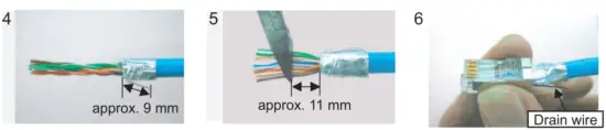 | ||
| Fold back drain wire and cut it, leaving approx. 9 mm. | Straighten and flatten the cores in colored order and cut them, leaving approx. 11 mm. | Insert the cable into the modular plug so that the folded part of the shield enters into the plug housing. The drain wire should be located on the tab side of the jack. |
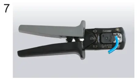
Using special crimping tool MPT5-8AS (PANDUIT CORP.), crimp the modular plug. Finally, check the plug visually.
TTYCSLA cable
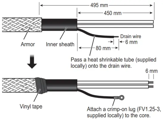
How to connect wires to a terminal connector
Procedure
- Twist the cores.
- Press the terminal opener downward.
- Insert the wire in the hole.
- Remove the terminal opener.
- Pull the wire to confirm that it is secure.
2.1.4 How to change the fuse
Change the fuse in the fuse holder on the power cable according to the input voltage, referring to the following table. Fuses are supplied as spare parts.
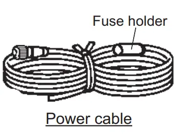
![]() WARNING
WARNING![]() Use the proper fuse.
Use the proper fuse.
Fuse rating is shown in the table below. Use of a wrong fuse can result in damage to the equipment.
| Input voltage | Rating of fuse |
| 12 VDC | 15 A (factory default) |
| 24 VDC | 7:00 AM |
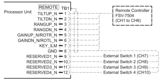
2.1.5 External switch connection
External switches can be connected to the TB1 terminal in the processor unit to provide one-touch access to a desired menu item or menu. Up to four external switches, each with an individual function can be connected. Use a push button switch (momentary contact) for the external switch. For how to assign the function to the external switch, see the operator’s manual.
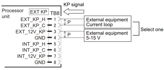
2.1.6 External KP connection
Note: To use the 3D functions, output the KP signal from the transceiver unit to external equipment. If the KP (Keying Pulse) signal is synchronized with external equipment, the 3D function may not work properly.
KP input
To synchronize the KP (Keying Pulse) signal from external equipment, make the connection as follows:
• When the external equipment is a current drive circuit: Use the TB8-1 and TB8-2.
• When the external equipment is a voltage drive circuit: Use the TB8-3 and TB8-4. The signals for current and voltage drive circuits cannot be used simultaneously.
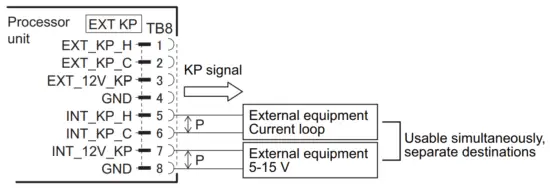
KP output
To output the KP signal from the transceiver unit to external equipment, make the connection as follows:
• When the external equipment is a current drive circuit: Use the TB8-5 and TB8-6.
• When the external equipment is a voltage drive circuit: Use the TB8-7 and TB8-8.
The signals for the current and voltage drive circuits can be used simultaneously, for separate destinations.
2.2 Control Unit
Connect the control unit to the J1 or J2 terminal in the processor unit.
Ground the control unit, using a ground wire (IV-1.25sq., supplied locally).
2.3 Transceiver Unit
2.3.1 Internal wiring and cable clamp position
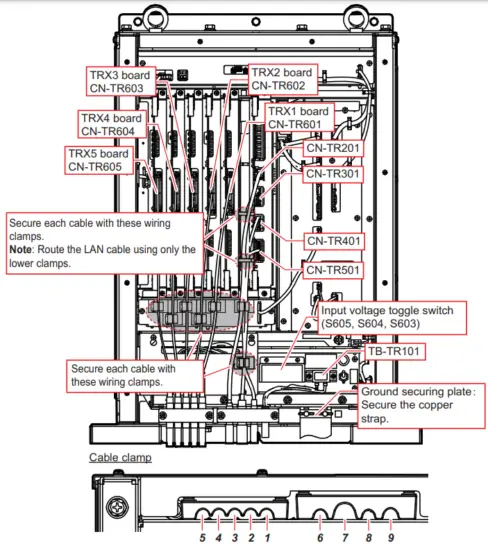
| Clamp position | Connect to | Cable from | Cable |
| / | CN-TR601 | Matching box | 10CA10110 |
| 2 | CN-TR602 | ||
| 3 | CN-TR603 | ||
| 4 | CN-TR604 | ||
| 5 | CN-TR605 | ||
| 6 | CN-TR201 | Processor unit | DTIC5E350SLABVCVxxT* |
| 7 | CN-TR401 | Control box | 10CA10147 |
| CN-TR501 | |||
| 8 | CN-TR301 | Processor unit | 1032380* |
| 9 | TB-TR101 | 100/110/115/230/230 VAC | DPYCY-2.5* |
*: Fabricate the cables referring to section 2.3.2.
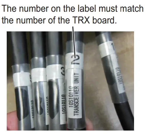
Cable from matching box (10CA10110 cable)
The labels on each 10CA10110 cable from The matching box indicate where to connect the cable. For example, the cable labeled “TRANSCEIVER UNIT 2” is connected to the TRX2 board (CNTR602).
Notice before turning the power on
Before turning the power on, switch the input voltage toggles (S603, S604, S605) according to the input voltage. This prevents the incorrect voltage from being input to the transceiver unit. For details about the input voltage toggle switch, see section 2.3.3.
2.3.2 Cable fabrication
10S2380 cable
Fabricate the cable referring to section 2.1.3.
LAN cable
Fabricate the cable referring to section 2.1.3.
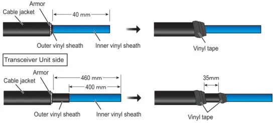
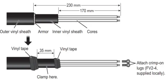
DPYCY-2.5 cable
Fabricate the cable as shown in the following figure.
2.3.3 Input voltage
The transceiver unit is shipped from the factory with the input voltage set for 230 VAC. If your vessel uses a different voltage, change the toggle switches referring to the following table.
| Input voltage | S605 | S604 | S603 |
| 100V | L | L | L |
| 110V | L | L | H |
| 115V | L | H | H |
| 220V | H | L | H |
| 230V (default) | H | H | H |
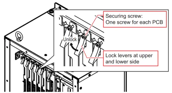
2.3.4 Removing and inserting a printed circuit board
To remove a printed circuit board in the transceiver unit, unfasten the securing screw and unlock the lock lever.
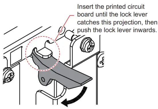
To insert a printed circuit board, insert the board until the lock lever catches on the upper and lower projection, then push the lock lever inwards (see the following figure).
After the board is locked in place with the lock lever, confirm that the inside end of the securing screw is firmly against the chassis, then fasten the securing screw. If the screw is not firmly against the chassis, the board may be inserted incorrectly. Remove and re-insert the board.
2.4 Control Box
Note 1: To prevent accidents and injury while conducting maintenance or wiring, turn the control box off at the breaker.
Note 2: If the wiring for the motor and brake is incorrect, the transducer may be lowered unintentionally. Check the interconnection diagram at the back of this manual or wiring label on the rear side of the control box cover to confirm that the internal wiring is correct before turning the power on.
2.4.1 Internal wiring and cable clamp position
The connection LED lights up in red color to indicate that the wiring is correct. Confirm that the LED is lit. If the LED is not lit, disconnect the power cables and reconnect them correctly. Re-apply the power and confirm that the LED is lit.
The hull unit does not work if the connections are incorrect.
- Power connected correctly: LED lights in red.
- Incorrect connection: LED does not light.
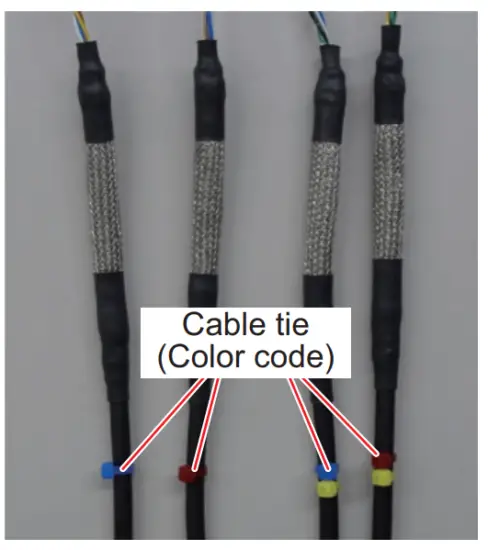
| Clamp position | Cable | Color code *³ | Connect to | Cable from |
| When the control box is mounted to the hull unit | ||||
| 1 | 10CA10133 | Blue | TB1 HFLT ) | Rotation motor |
| 10CA10134 | Red | Pitch motor | ||
| 2 | TPYCY-4*¹ | TB1 (Power) | Ship’s supply | |
| 3-1 | Limit Switch | – | TB5 | Sensor |
| Emergency Stop Button | – | TB7 | ||
| Ratchet Wrench | TB7 | |||
| 3-2 | Encoder | – | TB6 | |
| 4 | 2PCNT 5X2SQ | – | TB1 (Power) | Motor |
| 5 | 10CA10147*2 | – | TB1 (HCTL)/TB2 | Transceiver unit |
| 6 | 10CA10135 | Yellow/Blue | TB8 | Rotation resolver |
| 10CA10136 | Yellow/Red | TB10 | Pitch resolver | |
| 7 | 10CA10141 | Yellow | TB4 | Motion sensor |
| 8 | Signal light | – | TB3 | Signal light (supplied locally) |
| 9 | Not used | – | – | – |
| 10 | Not used | – | – | – |
| II | Not used | – | – | – |
| When mounting the control box separately from the hull unit | ||||
| 1 | 10CA10137*2 | Blue | TB1 (HFLT) | Rotation motor |
| 10CA10138*2 | Red | Pitch motor | ||
| 2 | TPYCY-4*¹ | – | TB1 (Power) | Ship’s power supply |
| 3 | 10CA10127*¹ | – | TB5/TB6 | Sensor |
| 4 | FA-TPYCY-4*¹ | – | TB1 (Power) | Motor |
| 5 | 10CA10147*2 | – | TB1 (HCTL)/TB2 | Transceiver unit |
| 6 | 10CA10139*2 | Yellow/Blue | TB8 | Rotation resolver |
| 10CA10140*2 | Yellow/Red | TB10 | Pitch resolver | |
| 7 | Not used | Yellow | Motion sensor | |
| 8 | Not used | – | ||
| 9 | PNCTF-S 4CX0.75*1 | – | TB1 (Power) | Brake |
| 10 | Not used | – | – | |
| 11 | 10CA10128*l | – | TB3/TB4/TB7 | Sensor |
* 1: Fabricate the cables referring to section 2.4.2.
* 2: Attach terminal connectors referring to section 2.4.3.
*3: Color code indicates the color of the cable tie attached to the cable end. This color is used to identify the cables.
2.4.2 Cable fabrication
TPYCY-4 cable (power cable)
Control Box side
FA-TPYCY-4 cable (between the control box and extension box)
Control Box and Extension Box side
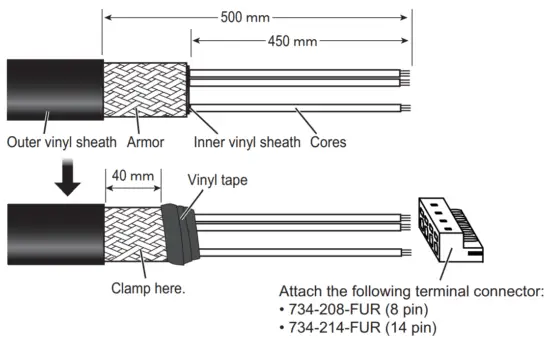
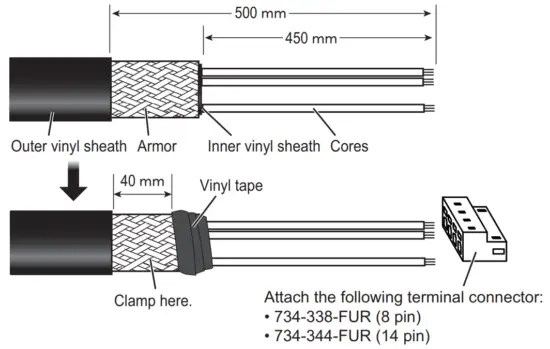
10CA10127 cable
Fabricate the COSPEVVSBC 12PX0.2LF (10S10166) cable as follows to make the 10CA10127 cable.
Control Box side
| Pair No. | Core color fl | Connect to | Core color 2-1 | Connect to |
| 1 | White | TB5-1 | Blue | TB5-2 |
| 2 | White | TB5-3 | Green | TB5-4 |
| 3 | White | TB5-5 | Yellow | TB5-6 |
| 4 | White | TB5-7 | Brown | TB5-8 |
| 5 | Black | TB5-9 | Blue | TB5-10 |
| 6 | Black | TB5-11 | Green | TB5-12 |
| 7 | Black | TB5-13 | Yellow | TB5-14 |
| 8 | Black | TB6-2*2 | Brown | TB6-2*2 |
| 9 | Red | TB6-1 *2 | Blue | TB6-1 *2 |
| 10 | Red | TB6-3 | Green | TB6-4 |
| 11 | Red | TB6-5 | Yellow | TB6-6 |
| 12 | Red | TB6-7 | Brown | TB6-8 |
*1: Core color 1 and core color 2 indicate the wire from a twisted pair to be used.
* 2 : TB6-1 and TB6-2 use two wires for each pin.
Extension Box side
| Pair No. | Core color 1*¹ | Connect to | Core color 2*¹ | Connect to |
| 1 | White | J2-1 | Blue | J2-2 |
| 2 | White | J2-3 | Green | J2-4 |
| 3 | White | J2-5 | Yellow | J2-6 |
| 4 | White | J2-7 | Brown | J2-8 |
| 5 | Black | J2-9 | Blue | J210 |
| 6 | Black | J2-11 | Green | J2-12 |
| 7 | Black | J2-13 | Yellow | J2-14 |
| 8 | Black | J1-2*2 | Brown | J1-2*2 |
| 9 | Red | J1-1*2 | Blue | J1-1*2 |
| 10 | Red | J1-3 | Green | J1-4 |
| 11 | Red | J1-5 | Yellow | J1-6 |
| 12 | Red | J1-7 | Brown | J1-8 |
*1: Core color 1 and core color 2 indicate the wire from a twisted pair to be used.
*2: J1-1 and J1-2 use two wires for each pin.
10CA10128 cable
Fabricate the COSPEVVSBC 12PX0.2LF (10S10166) cable as follows to make the 10CA10128 cable.
Control Box side
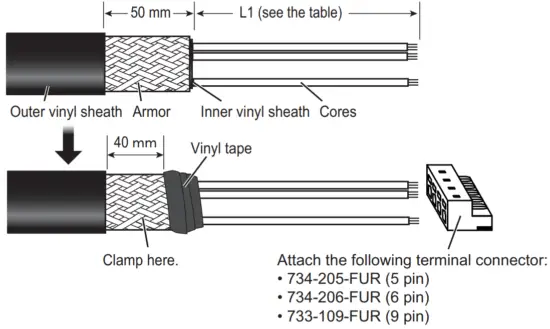
| Pair No. | Core color 1* | L1 | Connect to | Core color 2* | L1 | Connect to |
| 1 | White | 500 mm | TB4-5 | Blue | 500 mm | TB4-7 |
| 2 | White | 500 mm | TB4-6 | Green | 500 mm | TB4-8 |
| 3 | White | 500 mm | TB4-1 | Yellow | 500 mm | TB4-2 |
| 4 | White | 0 mm | – | Brown | 500 mm | TB4-3 |
| 5 | Black | 0 mm | – | Blue | 0 mm | – |
| 6 | Black | 700 mm | TB3-6 | Green | 700 mm | TB3-5 |
| 7 | Black | 700 mm | TB3-1 | Yellow | 700 mm | TB3-2 |
| 8 | Black | 700 mm | TB3-3 | Brown | 700 mm | TB3-4 |
| 9 | Red | 0 mm | – | Blue | 0 mm | – |
| 10 | Red | 0 mm | – | Green | 0 mm | – |
| 11 | Red | 400 mm | TB7-1 | Yellow | 400 mm | TB7-2 |
| 12 | Red | 400 mm | TB7-4 | Brown | 400 mm | TB7-5 |
*: Core color 1 and core color 2 indicate the wire from a twisted pair to be used.
Extension Box side
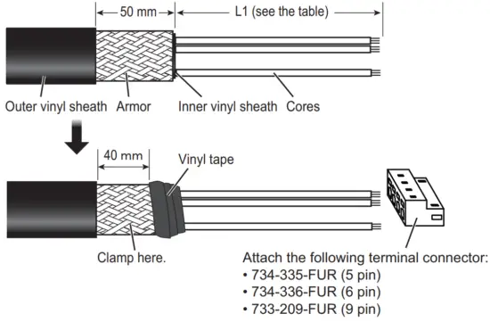
| Pair No. | Core color 1* | L1 | Connect to | Core color 2* | L1 | Connect to |
| 1 | White | 450 mm | J4-5 | Blue | 450 mm | J4-7 |
| 2 | White | 450 mm | J4-6 | Green | 450 mm | J4-8 |
| 3 | White | 450 mm | J4-1 | Yellow | 450 mm | J4-2 |
| 4 | White | 0 mm | – | Brown | 450 mm | J4-3 |
| 5 | Black | 0 mm | – | Blue | 0 mm | – |
| 6 | Black | 450 mm | J5-6 | Green | 450 mm | J5-5 |
| 7 | Black | 450 mm | J5-1 | Yellow | 450 mm | J5-2 |
| 8 | Black | 450 mm | J5-3 | Brown | 450 mm | J5-4 |
| 9 | Red | 0 mm | – | Blue | 0 mm | – |
| 10 | Red | 0 mm | – | Green | 0 mm | – |
| 11 | Red | 450 mm | J3-1 | Yellow | 450 mm | J3-2 |
| 12 | Red | 450 mm | J3-4 | Brown | 450 mm | J3-5 |
*: Core color 1 and core color 2 indicate the wire from a twisted pair to be used.
PNCTF-S 4CX0.75 cable
Control Box and Extension Box side
2.4.3 Attaching the terminal connector
Attach the terminal connector to the cable end, referring to the following figure.
How to connect wires to a terminal connector
Procedure
- Twist the cores.
- Press the terminal opener downward.
- Insert the wire in the hole.
- Remove the terminal opener.
- Pull the wire to confirm that it is secure.
The following table shows the terminal connector for each cable.
| Cable | Control box side | Extension box side | ||
| Terminal connector | Connect to | Terminal connector | Connect to | |
| 10CA10127 | 734-214-FUR (14 pin) | TB5 | 734-344-FUR (14 pin) | J2 |
| 734-208-FUR (8 pin) | TB6 | 734-338-FUR (8 pin) | J1 | |
| 10CA10128 | 734-206-FUR (6 pin) | TB3 | 734-336-FUR (6 pin) | J5 |
| 733-109-FUR (9 pin) | TB4 | 733-209-FUR (9 pin) | J4 | |
| 734-205-FUR (5 pin) | TB7 | 734-335-FUR (5 pin) | J3 | |
| 10CA10137 | 734-209-FUR (9 pin) | TB1 (HFLT board) | – 734-339-FUR (9 pin) | J9 |
| 10CA10138 | ||||
| 10CA10139 | 733-106-FUR (6 pin) | TB8 | 733-206-FUR (6 pin) | J6 |
| 10CA10140 | 733-110-FUR (10 pin) | TB10 | 733-210-FUR (10 pin) | J8 |
| 10CA10147 | 733-108-FUR (8 pin) | TB1 (HCTL board) | – | – |
| 733-112-FUR (12 pin) | TB2 | – | – | |
Note: The terminal opener and wire length used are different for each terminal connector. See the following table.
| Terminal Connector | Terminal opener | Recommended wire length to be exposed |
| White terminal connector (733 series) | Yellow terminal opener | 5 to 6 mm |
| Orange terminal connector (734 series) | White terminal opener | 7 mm |
2.4.4 How to connect the signal light
Connect a signal light (supplied locally) to TB3 in the control box. Contact specifications of this equipment are as follows. Select an appropriate signal light.
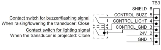
| Pin No. | Signal | Description | Remarks |
| 1 | GND | GND | – |
| 2 | 24V | Power output (24 VDC) | 24 VDC, steady-state current 1.0 A or less |
| 3 | CONTROL GND | GND for TB3-4 and TB3-5 | – |
| 4 | CONTROL_LIGHT | Contact output for lighting signal | 60 VDC, 0.5 A or less |
| 5 | CONTROL_BUZZ | Contact output for buzzer/flashing signal | 60 VDC, 0.5 A or less |
| 6 | SHIELD | Open | – |
The following example uses the recommended signal light (PEW-24AB, manufacturer: PATLITE).
Note: For signal lights other than the recommended product, refer to the signal light’s wiring diagram before connecting the light to the FSV-75.
Recommended signal litht
· Model: PEW-24AB
· Manufacturer: PATLITE
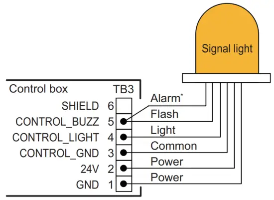
| Hull unit status | Signal light status |
| Raising/Lowering | Flashes and alarm sounds |
| Projected | ON |
| Retructed | OFF |
- : If the alarm sound is not required when lowering/raising the transducer, set the alarm signal as open.
2.4.5 Contact output
TB5-1 and TB5-2 in the control box can output a contact signal. Contact specifications of this equipment are as follows:
Contract specifications
- When the transducer is retracted: Open
- Others: Closed
Contact rating
- 125 VAC, 3 A or less
- 30 VDC, 1.5 A or less
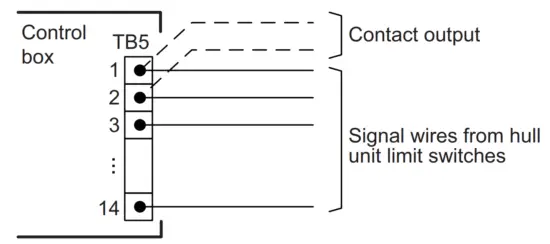
Note: To use the contact signal from TB5, twist the contact output wires with the hull unit limit switch wires, then connect the wires to TB5-1 and TB5-2.
2.5 Matching Box
Connect the transducer cable (10CA10144) and transceiver unit cable (10CA10110, ×5) to the connectors in the matching box.
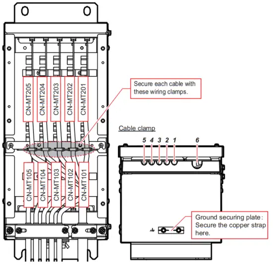
| Clamp position | Cable | Connect to | Cable from |
| / | 10CA10110 (No.1) | CN-MT101 | Transceiver unit |
| 2 | 10CA10110 (No.2) | CN-MT102 | |
| 3 | 10CA10110 (No.3) | CN-MT103 | |
| 4 | 10CA10110 (No.4) | CN-MT104 | |
| 5 | 10CA10110 (No.5) | CN-MT105 | |
| 6 | 10CA10144 | CN-MT201 CN-MT202 CN-MT203 CN-MT204 CN-MT205 | Transducer |
A label is attached to each cable end, indicating the connector number to be used. Connect each cable according to its label.
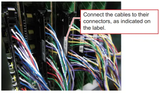
2.6 Extension Box
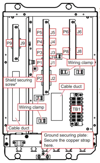
*: Fasten the shield of the cable that is connected to P1.
After connecting the terminal connectors, place the connectors in position, then attach the securing plate to secure the connectors.
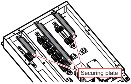
After wiring, pass each cable through the cable duct and wiring clamp.
Cable clamp
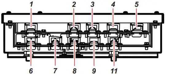
| Clamp position | Cable | Connect to | Cable from |
| / | 10CA10133 | P9 (9 pin) | Control box |
| 10CA10134 | P9 (9 pin) | ||
| 2 | 10CA10127*1 | J1 (8 pin) J2 (14 pin) | |
| 3 | 10CA10128*1 | J3 (5 pin) J4 (9 pin) J5 (6 pin) | |
| 4 | 10CA10139*2 | J6 (6 pin) | |
| 5 | 10CA10140*2 | J8 (10 pin) | |
| FA-TPYCY-4*1 | TB1 | ||
| PNCTF-S 4CX0.75*1 | TB1 | ||
| 6 | 10CA10137*2 | J9 (9 pin) | Rotation motor |
| 10CA10138*2 | J9 (9 pin) | Pitch motor | |
| 7 | Emergency stop button | P3 (5 pin) | Sensor |
| Ratchet wrench | P3 (5 pin) | ||
| Signal light | P5 (6 pin) | ||
| 10CA10141 | P4 (9 pin) | ||
| 8 | Limit switch | P2 (14 pin) | Sensor |
| Rotary encoder | P1 (8 pin) | ||
| 9 | 10CA10135 | P6 (6 pin) | Rotation resolver |
| 10CA10136 | P8 (10 pin) | Pitch resolver | |
| 10 | 2PCNT 5X2SQ | TB1 | Raise/lower motor |
*1: Fabricate the cables referring to section 2.4.2.
*2: Attach terminal connectors referring to section 2.4.3.
2.7 Input/Output Sentences (NMEA0183)
This equipment can input/output the following sentences:
| Sentence | Data | NMEA0183 Version |
| Input sentences | ||
| CUR | Water Current Layer | Ver.1.5/2.0/3.0/4.0/4.1 |
| DBS | Depth Below Surface | Ver.1.5/2.0/3.0/4.0/4.1 |
| DBT | Depth Below Transducer | Ver.1.5/2.0/3.0/4.0/4.1 |
| DPT | Depth | Ver.1.5/2.0/3.0/4.0/4.1 |
| GGA | Global Positioning System Fix Data | Ver.1.5/2.0/3.0/4.0/4.1 |
| GLL | Geographic Position | Ver.1.5/2.0/3.0/4.0/4.1 |
| GNS | GNSS Fix Data | Ver.1.5/2.0/3.0/4.0/4.1 |
| HDG | Heading, Deviation & Variation | Ver.1.5/2.0/3.0/4.0/4.1 |
| HDM | Heading, Magnetic | Ver.1.5/2.0/3.0/4.0/4.1 |
| HDT | Heading True | Ver.1.5/2.0/3.0/4.0/4.1 |
| MDA | Meteorological Composite | Ver.1.5/2.0/3.0/4.0/4.1 |
| MTW | Water Temperature | Ver.1.5/2.0/3.0/4.0/4.1 |
| MWV | Wind Speed and Angle | Ver.1.5/2.0/3.0/4.0/4.1 |
| RMC | Recommended minimum Specific GNSS Data | Ver.1.5/2.0/3.0/4.0/4.1 |
| THS | True Heading and Status | Ver.1.5/2.0/3.0/4.0/4.1 |
| Sentence | Data | NMEA0183 Version |
| VBW | Dual Ground/Water Speed | Ver.1.5/2.0/3.0/4.0/4.1 |
| VDR | Set & Drift | Ver.1.5/2.0/3.0/4.0/4.1 |
| VHW | Water Speed and Heading | Ver.1.512.013.0/4.0/4.1 |
| VTG | Pitch and Roll | Ver.1.5/2.0/3.0/4.0/4.1 |
| VWR | Relative (Apparent) Wind Speed and Angle | Ver.1.5/2.0/3.0/4.0/4.1 |
| VWT | True Wind Speed Angle | Ver.1.5/2.0/3.0/4.0/4.1 |
| ZDA | Time and Date | Ver.1.5/2.0/3.0/4.0/4.1 |
| Output sentences | ||
| TLL | Target Latitude and Longitude | Ver.1.5/2.0/3.0/4.0/4.1 |
| evt | FURUNO proprietary sentence | – |
| fkv | FURUNO proprietary sentence | – |
| fmg | FURUNO proprietary sentence | – |
| fvc | FURUNO proprietary sentence | – |
| pidat | FURUNO proprietary sentence | – |
| sht | FURUNO proprietary sentence | – |
| tfm | FURUNO proprietary sentence | – |
| Um | FURUNO proprietary sentence | – |
| tqm | FURUNO proprietary sentence | – |
ADJUSTMENTS
3.1 DIP Switch Settings in the Processor Unit
When a monitor is connected via a video distributor or matrix switcher, the resolution may not display correctly. If this occurs, change the DIP switch settings for SW4/SW5
on the PCRI board. The changed settings fix the output to SXGA.
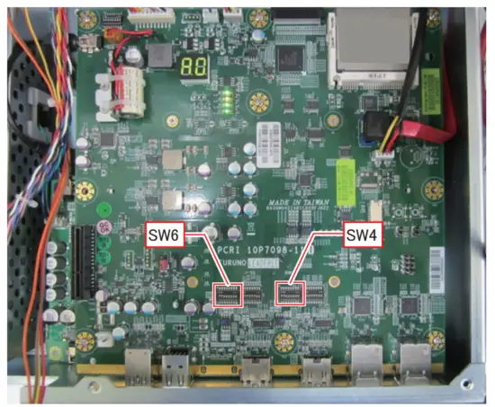
Note: Only use the settings outlined in the following table.
| 1 | 2 | 3 | 4 | 5 | 6 | 7 | 8 | Remarks |
| DIP switch SW4 is used for setting the output resolution from HDMI1. | ||||||||
| ON | ON | OFF | OFF | OFF | OFF | OFF | OFF | HDMI1 port outputs at the maximum resolution of the monitor connected to the processor unit (factory default). |
| OFF | OFF | ON | ON | OFF | OFF | OFF | OFF | HDMI1 port outputs SXGA. |
| DIP switch SW6 is used for setting the output resolution from HDMI2. | ||||||||
| ON | ON | OFF | OFF | OFF | OFF | OFF | OFF | HDMI2 port outputs at the maximum resolution of the monitor connected to the processor unit (factory default). |
| OFF | OFF | ON | ON | OFF | OFF | OFF | OFF | HDMI2 port outputs SXGA. |
3.2 How to Change the Displayed Language
The language in which the menus and indications are displayed can be changed. This unit is shipped with the language set to English.
- Press the MENU/ESC key to open the menu.

- Select [9 Installation Setting].
The following confirmation message appears.
- Select [OK].

- Select [8 Initialization].
The following confirmation message appears.
- Select [OK].

- Select [1 Language].
- Select the appropriate language.
- Select [Quit].
- Press and hold the MENU/ESC key to close the menu.

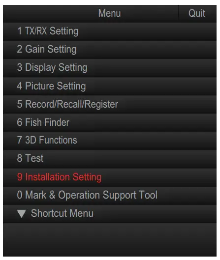
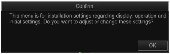
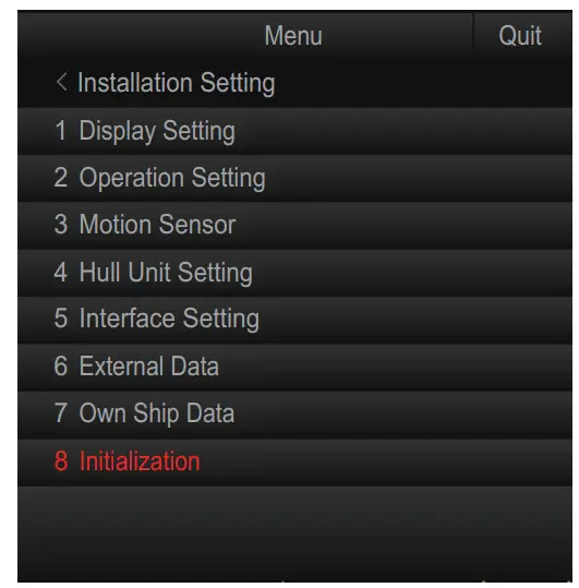

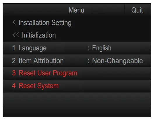

3.3 How to Register the Transducer Position
To display the distance which the transducer is protruded, the limit switch location must be entered at the processor unit.
This setting requires the transducer to be protruded from a fully retracted position.
Make sure there is sufficient room for full protrusion.
- Press the MENU/ESC key to open the menu.

- Select [9 Installation Setting].
The following confirmation message appears.
- Select [OK].

- Select [4 Hull Unit Setting].

- Select [1 REG TD Position].
The following confirmation message appears. Note: When the transducer position is already registered, the following message appears. To re-register the transducer position, select [Next] the left click.
- Confirm that transducer is retracted, then select [Next].

- Confirm that the transducer can be protruded fully, then select [Next].

- Check the safety and press the
 (Full-protrude) key to protrude the transducer.
 - When the transducer is at full protrusion, select [Next].

- Press the
 (Retract) key to retract the transducer.
 - Select [Quit].
Note: If transducer registration is aborted for any reason, the following message appears. Select [Quit] to close the message and restart the procedure once safety is ensured.
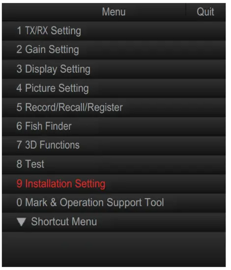
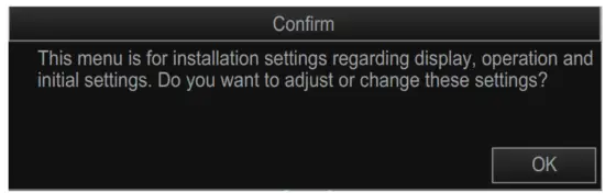
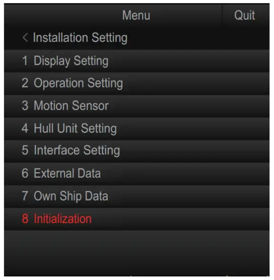
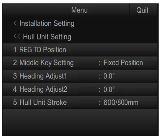
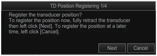 Note: When the transducer position is already registered, the following message appears. To re-register the transducer position, select [Next] the left click.
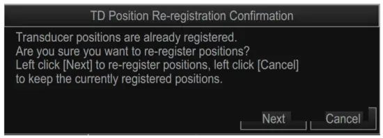
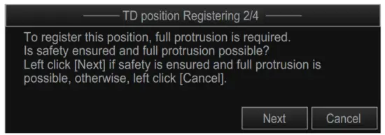
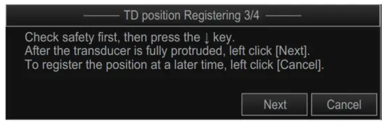
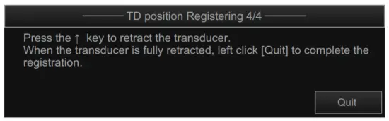
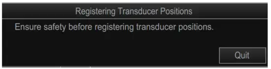
3.4 Hull Unit Checks
Note 1: To avoid damage to the equipment, do not transmit while dry-docked.
Note 2: When performing maintenance to the hull unit and checking the movement, make sure that only the hull unit is powered and perform all checks in test mode to avoid accident or injury.
Note 3: Make sure all connections to the hull unit are made correctly, referring to the wiring table attached to the hull unit, to prevent the shaft from being dislodged.
How to check to transmit status Transmission is set to [OFF] as factory default. You can check and change the status by doing the following.
- Press the MENU/ESC key to open the menu.
- Select [8 Test].
- Select [9 Transmission].

- Select the appropriate setting.
- Select [Quit].
- Press and hold the MENU/ESC key to close the menu.
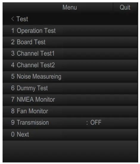
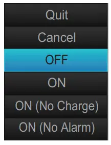
How to check the hull unit
- Press the power button to turn the power on, then check that the LEDs located to the left of the power button and (Retract) key are turned on.

- Confirm that the “3.3V” and “UP” LEDs on the control box are on.

- Remove the control box cover and check the terminal voltage as shown in the following table.

Terminal block Terminal No. Voltage TB1 (1) – (2) 220 VAC (2) – (3) 220 VAC (1) – (3) 220 VAC - Set the TEST/NORMAL switch on the control panel to [TEST], then press the DOWN switch to confirm that the transducer lowers. Also, while the transducer is being lowered, check that the “HTX” LED lights when the TX limit switch is passed by the transducer shaft.
Note: The TX limit switch does not stop the transducer when the TEST/NORMAL switch is in the [TEST] position. - Release the DOWN switch during lowering to confirm that the transducer stops lowering.
- Press the DOWN switch again to continue lowering. While the transducer is lowering, press the EMERGENCY STOP button, then confirm that the transducer has stopped. After confirming that the transducer has stopped, turn the EMERGENCY STOP button to release the transducer.
- Press the DOWN switch again to continue lowering. While the transducer is lowering, press the lower limit switch, then confirm that the transducer has stopped.
- Press the UP switch to raise the transducer and conduct the same tests as when lowering.
- Remove the ratchet wrench from its holder on the top of the hull unit. Press the UP switch, then the DOWN switch to make sure the hull unit does not move. Once you have confirmed there is no movement in the hull unit, place the ratchet wrench back in its holder.

- Check the following items in the control panel:
• Each of the LEDs, for UP, HTX, and DN, lights when their respective limit switch is pressed.
• “UP” LED lights when the UP switch is pressed.
• “DOWN” LED lights when the DOWN switch is pressed. - After the above tests are completed, switch the TEST/NORMAL switch back to [NORMAL] on the control panel.
- Press the (mid-protrusion) key and check that the hull unit is lowered to the halfway point. While lowering, check that the LED on the left of the (mid-protrusion) key is flashing, the limiter makes a short beep sound, and once the shaft stops at halfprotrude the LED lights constantly.
- Using the same method, check that the (Full-protrude) key and (Retract) key LEDs flash and light constantly and that the limit switch beeps.
- Press the power switch on the control unit to turn the power off and check that the transducer is retracted automatically. At full retraction, check that the power is off.
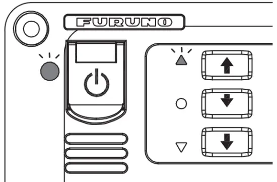
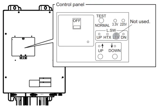
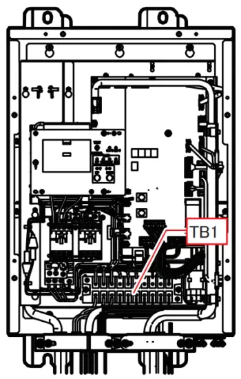
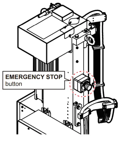
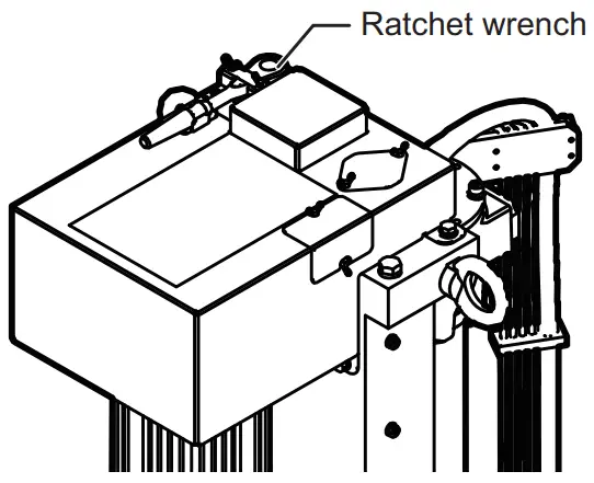
3.5 How to Adjust the Heading
Adjust the heading so an echo which is dead ahead appears dead ahead on the display as follows:
Note: The transducer should be aligned with the bow at installation (see section 1.2.9). This procedure provides finer adjustments to the alignment.
- Enable transmission as shown in section 3.4.
- Find a target in the bow direction (buoy, for example) and display it at a near range. If the target appears at 12 o’clock the heading alignment is correct. If it does not, measure the error and go to the next step.

- If the heading is skewed, measure the skew angle.
- Press the MENU/ESC key to open the menu.
- Select [9 Installation Setting]. A confirmation message appears.
- Select [OK].
- Select [4 Hull Unit Setting].
- Select [3 Heading Adjust 1].
- Adjust the setting so that the target selected at step 2 appears at the 12 o’clock position on-screen. A positive value corrects the heading in the clockwise (right) direction, a negative value corrects in the anticlockwise (left) direction.
 Note: Heading alignment also changes the turning range of the transducer. When the heading is not adjusted ([3 Heading Adjust 1] = [0°]), the turning range is -175° to +175°. For example, if [3 Heading Adjust 1] is set to [20°], the turning range is also changed to -195° to +155°.
 - Select [Quit].
- Select [4 Heading Adjust 2].
- Adjust the direction offset of the motion sensor.
The [Reference Direction] mark on the motion sensor should face the ship’s bow.
For example, when the mark is skewed 2° in the starboard direction, enter “+2°”. - Select [Quit].
- Press and hold the MENU/ESC key to close the menu.
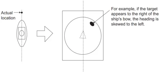
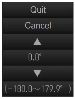 Note: Heading alignment also changes the turning range of the transducer. When the heading is not adjusted ([3 Heading Adjust 1] = [0°]), the turning range is -175° to +175°. For example, if [3 Heading Adjust 1] is set to [20°], the turning range is also changed to -195° to +155°.
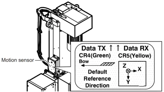
3.6 How to Set the Stroke of the Hull Unit
Select the stroke (length) of your hull unit as follows.
- Press the MENU/ESC key to open the menu.
- Select [9 Installation Setting]. A confirmation message appears.
- Select [OK].
- Select [4 Hull Unit Setting].
- Select [5 Hull Unit Stroke].
- Select [600/800 mm] or [1100 mm].
- Select [Quit].
- Press and hold the MENU/ESC key to close the menu.

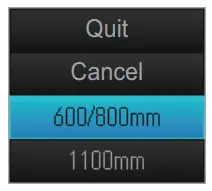
3.7 How to Configure the Own Ship Mark
To show your own ship mark accurately on-screen, set your ship’s dimensions and the position of the transducer with the following procedure.
- Press the MENU/ESC key to open the menu.
- Select [9 Installation Setting].
A confirmation message appears. - Select [OK].
- Select [7 Own Ship Data].
- Adjust each setting item.
• [Ship’s Length]: The length of the ship.
• [Ship’s Width]: The width of the ship at its widest point.
• [TD Position 1]: Distance from the transducer to bow.
• [TD Position 2]: Distance from the transducer to keel. Set a positive value for starboard installations, a negative value for port installations.
- Press and hold the MENU/ESC key to close the menu.
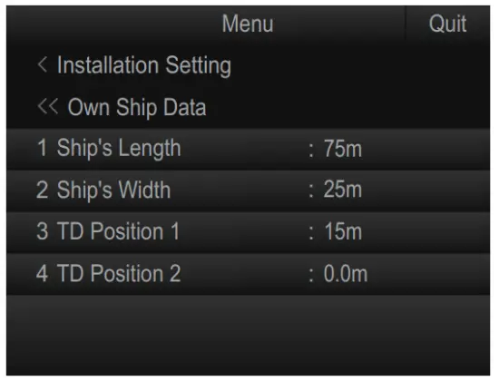
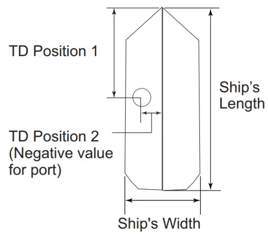
3.8 How to Set Up a Secondary Monitor
When a secondary monitor is connected, use the following procedure to adjust the display settings.
- Press the MENU/ESC key to open the menu.
- Select [9 Installation Setting].
A confirmation message appears. - Select [OK].
- Select [1 Display Setting].

- Select [5 Monitor Setting].

- Select [1 2nd Monitor Setting].
- Select [Dual Display] or [Sub Display] as appropriate.
• [Dual Display]: Displays the full-screen slant mode display on the Sub monitor. Note that numeric/graphic data is not displayed on the Sub monitor.
• [Sub Display]: Displays the same screen as the Main monitor
When there is no secondary monitor connected, set this option to [OFF].
- Select [Quit].
The following confirmation message appears.
- Restart the system to apply the setting.
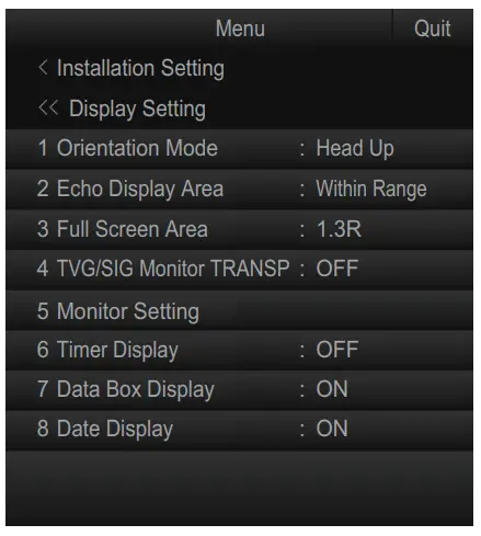
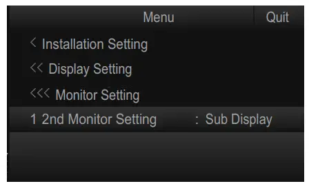
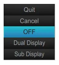

3.9 How to Export/Import Backup Data
3.9.1 How to export the backup data
Export the backup data to an external media as follows:
Note: Data backup requires the connection of an external media to the processor unit.
- With the MENU/ESC key pressed and held, press 1/F1, 3/F3, and 5/F5 in order. The system menu items appear on the main menu. Repeat the above procedure to hide the system menu items.
- Press the MENU/ESC key to open the menu.

- Select [Other Setting].

- Select [Backup Data].

- Select [Save to EXT Device].
The following message appears.
- Select [Change Destination].

- Specify the destination for the backup data, then click [OK].
- Select [Save].
The backup data is saved to the specified destination. - Press and hold the MENU/ESC key to close the menu.
- With the MENU/ESC key pressed and held, press 1/F1, 3/F3, and 5/F5 in order to hide the system menu items.
Note The error message “Disk space insufficient. Delete unnecessary files.” appears if the save destination does not have sufficient space for the backup data. If this ccurs, select [Delete Data] to delete unnecessary files, then repeat the above procedure.
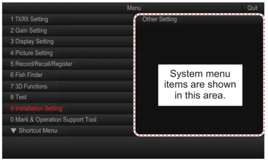
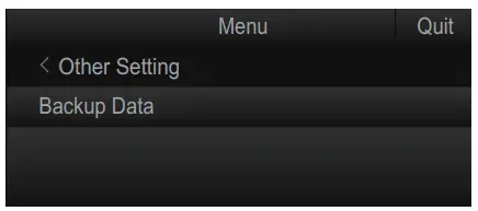
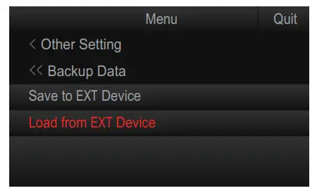
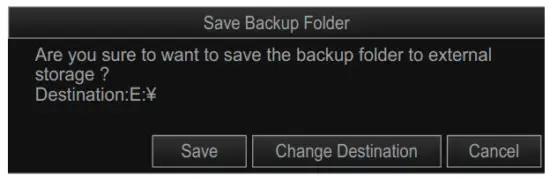
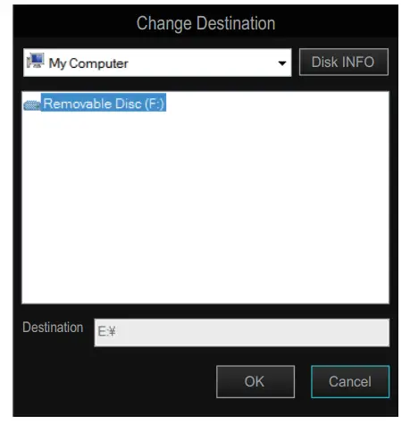
3.9.2 How to import the backup data
Note: Data import requires the connection of an external media to the processor unit.
- With the MENU/ESC key pressed and held, press 1/F1, 3/F3, and 5/F5 in order.
The system menu items appear on the main menu. Repeat the above procedure to hide the system menu items. - Press the MENU/ESC key to open the menu.
- Select [Other Setting].
- Select [Backup Data].
- Select [Load from EXT Device].
The following message appears.
- Select [OK].

- Select the backup folder to load, then click [Load].
The following confirmation message appears.
- Select [Update].
A confirmation message appears.
Note: Previous (old) backup data saved in the processor unit is overwritten and replaced when data is imported from an external source. - Restart the system to apply the setting.
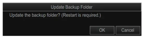
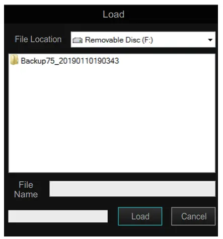
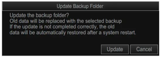
3.10 How to Backup/Load All Settings
3.10.1 How to backup all settings
You can backup all your menu settings (except language, IP address, date and time, oil replacement date, and motor running time) with the following procedure.
- Press the MENU/ESC key to open the menu.
- Select [5 Record/Recall/Register].
- Select [8 Setting File].
- Select [4 Save Ship’s Original].
The message “Are you sure to execute this item?” appears. - Select [Yes].
The file name, which appears in the [File Name] box, is automatically assigned as shown below.
FSV75_OriginalFile_yyyy_mm_dd_hh_mm_ss.ini
- Select where to save the setting data, from the drop-down list of destinations.
- Select [Save].
The progress bar shows the saving progress. After the settings are saved, the [Setting File] menu appears. - Press and hold the MENU/ESC key to close the menu.
Note: The error message “Disk space insufficient. Delete unnecessary files.” appears if the save destination does not have sufficient space (a minimum of 500MB is required). If this occurs, select [Delete Data] to delete unnecessary files, then repeat the above procedure.
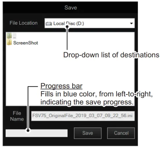
3.10.2 How to load backed-up settings
- Press the MENU/ESC key to open the menu.
- Select [5 Record/Recall/Register].
- Select [8 Setting File].
- Select [5 Recall Ship’s Original].
The message “Are you sure to execute this item? (Restart is required)” appears. - Select [Yes].

- Select the file to load, from the drop-down list of destinations.
The selected file appears in the [File Name] field. - Select [Load].
The progress bar shows the loading progress. After the settings are loaded, the message “Press the power key to restart.” appears. - Restart the system to apply the setting.
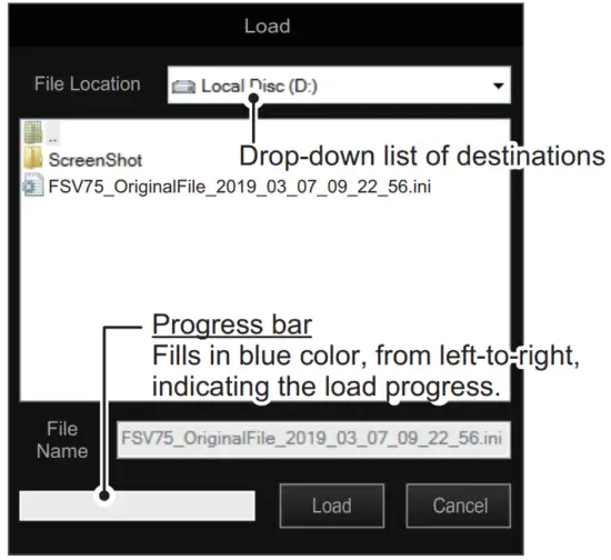
3.11 How to Change the IP Address for the Processor Unit and Transceiver Unit
To change the IP address for the processor unit and transceiver unit, do as follows:
Note: Only change the IP address when necessary. IP address changes may cause network errors.
- With the MENU/ESC key pressed and held, press 1/F1, 3/F3, 5/F5 in order.
The system menu items appear on the main menu. Repeat the above procedure to hide the system menu items. - Press the MENU/ESC key to open the menu.
- Select [9 Installation Setting].
A confirmation message appears. - Select [OK].

- Select [System Setting].

- Select [Processor Unit IP] or [Transceiver Unit IP].
The following message appears.
- Select [Yes].
- Adjust the setting value, then select [Quit].
The confirmation message appears. - Restart the system to apply the setting.

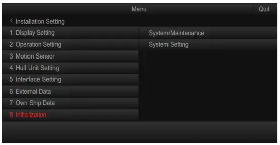
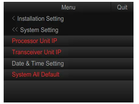
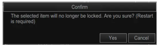
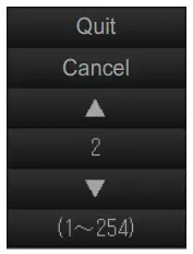
3.12 How to Set the System Time
Set the system time as follows:
- With the MENU/ESC key pressed and held, press 1/F1, 3/F3, 5/F5 in order.
The system menu items appear on the main menu. Repeat the above procedure to hide the system menu items. - Press the MENU/ESC key to open the menu.
- Select [9 Installation Setting].
A confirmation message appears. - Select [OK].
- Select [System Setting].
- Select [Date & Time].
- Set the time, date, and timezone as required.
Note: When the timezone setting is changed, the message “Press the power key to restart.” appears. Restart the system to apply the setting. - Press and hold the MENU/ESC key to close the menu.
- With the MENU/ESC key pressed and held, press 1/F1, 3/F3, 5/F5 in order to hide the system menu items.

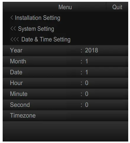
3.13 How to Restore Factory Default
Do as follows to restore factory default settings:
- With the MENU/ESC key pressed and held, press 1/F1, 3/F3, 5/F5 in order.
The system menu items appear on the main menu. Repeat the above procedure to hide the system menu items. - Press the MENU/ESC key to open the menu.
- Select [9 Installation Setting].
A confirmation message appears. - Select [OK].
- Select [System Setting].
- Select [System All Default].
The following confirmation message appears.
- Select [Yes] to restore factory default settings.
The following confirmation message appears. - Restart the system to apply the setting.
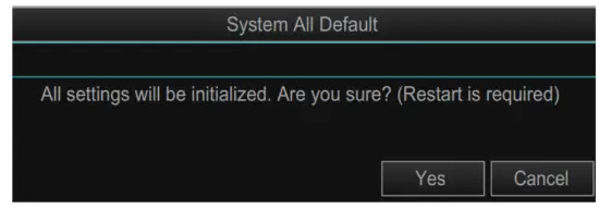

3.14 Error Code List
The error code list shows the possible errors for this equipment. Do as follows to open the error code list.
- With the MENU/ESC key pressed and held, press 1/F1, 3/F3, 5/F5 in order.
The system menu items appear on the main menu. Repeat the above procedure to hide the system menu items. - Press the MENU/ESC key to open the menu.
- Select [9 Installation Setting].
A confirmation message appears. - Select [OK].
- Select [System/Maintenance].

- Select [Error Code List].
The error code list appears.
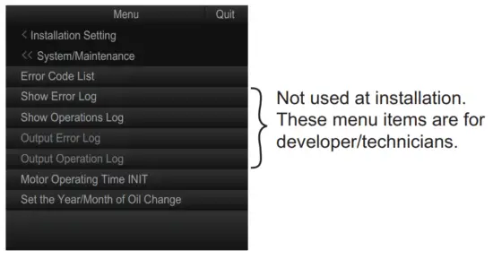
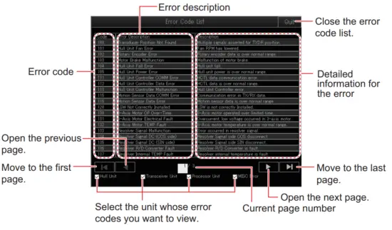
3.15 How to Register Motor Operating Times
The operating time for the rotation and pitch motors on the hull unit is recorded in the processor unit. Before replacing the processor unit, check the operating times on the
current processor unit and transfer the values to the new processor unit.
How to check the motor operating times
Check the motor operating times before replacing the processor unit
- Press the MENU/ESC key to open the menu.
- Select [8 Test].

- Select [0 Next].

- Select [4 Control Box Test].
- Check the [ACTIVE TIME] value for [ROTATE MOTOR] and [PITCH MOTOR].
- Press the MENU/ESC key to close the test screen.
- Press and hold the MENU/ESC key to close the menu.
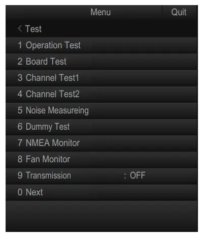
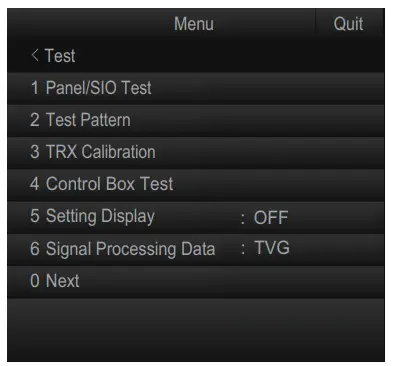
Registering the motor operating times
Register the motor operating times as follows:
- With the MENU/ESC key pressed and held, press 1/F1, 3/F3, 5/F5 in order.
The system menu items appear on the main menu. Repeat the above procedure to hide the system menu items. - Press the MENU/ESC key to open the menu.
- Select [9 Installation Setting].
A confirmation message appears. - Select [OK].
- Select [System/Maintenance].
- Select [Motor Operating Time INIT].

- Select [Rotate Motor].
- Register the operating time for the rotation motor, as recorded at
“How to check the motor operating times” on page 3-18. - Select [Quit] on the setting box.
- Similarly, register the operation time for the pitch motor ([Pitch Motor]).
- Press and hold the MENU/ESC key to close the menu.
- With the MENU/ESC key pressed and held, press 1/F1, 3/F3, 5/F5 in order to hide the system menu items.

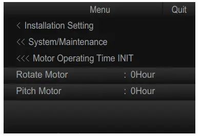
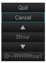
3.16 How to Set the Year/Month of Oil Change
The year and month at which the sonar oil is either filled (at installation) or replaced must be set within the menu. Also, if the processor unit is replaced, the year and month
must be transferred to the new processor unit. Set the year and month of oil change as follows:
- With the MENU/ESC key pressed and held, press 1/F1, 3/F3, 5/F5 in order.
The system menu items appear on the main menu. Repeat the above procedure to hide the system menu items. - Press the MENU/ESC key to open the menu.
- Select [9 Installation Setting].
A confirmation message appears. - Select [OK].
- Select [System/Maintenance].
- Select [Set the Year/Month of Oil Change].
Note: When replacing the processor unit, the year and date shown in this menu must be transferred to the new processor unit.
- Select [Year].
- Set the year of the sonar oil change.
- Select [Quit] on the setting box.
- Select [Month].
- Set the month of the sonar oil change.
- Select [Quit] on the setting box.
- Select [Message Timing].
- Set the message timing (unit: month).
A message, notifying the operator that oil replacement is required, appears on-screen when the months set here has passed from the date set in this menu. When [Message Timing] is set to “0”, the notifying message does not appear. - Select [Quit] on the setting box.
- Press and hold the MENU/ESC key to close the menu.
- With the MENU/ESC key pressed and held, press 1/F1, 3/F3, 5/F5 in order to hide the system menu items.

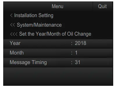
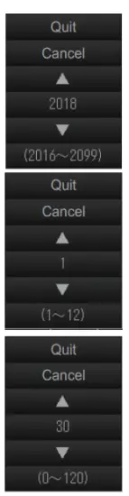
3.17 [Installation Setting] Menu
This section explains the menu items on the [Installation Setting] menu.
3.17.1 How to open the [Installation Setting] menu
- Press the MENU/ESC key to open the menu.

- Select [9 Installation Setting].
The following confirmation message appears.
- Select [OK].

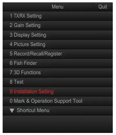
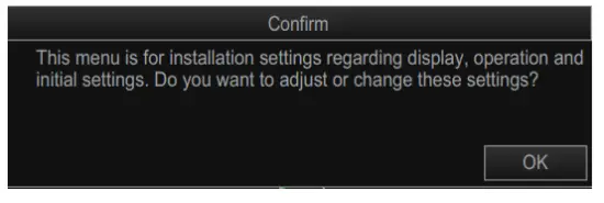
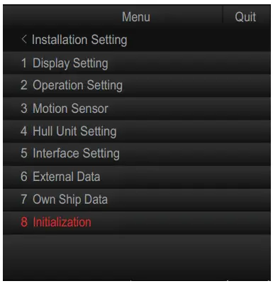
3.17.2 [Display Setting] menu
The [Display Setting] menu sets various display-related items according to the operator’s preference, To display this menu, select [1 Display Setting] from the [Installation Setting] menu.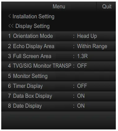
| Menu item | Remarks |
| [1 Orientation Mode] | Selects the orientation mode, among [Head-up], [North-up], [Course-up]. |
| [2 Echo Display Area] | Selects the echo display mode, [Within Range] or [Full Screen]. |
| [3 Full Screen Area] | Used when [2 Echo Display Area] is set to [Full Screen]. Expands the detection range and shows echoes outside the normal display area. Options are [1.3R], [1.6R], [1.9R] (R = ratio of increase in relation to currently selected range). |
| [4 TVG/SIG Monitor TRANSP] | Turns on/off the TVG monitor transparency. |
| [5 Monitor Setting] | Settings for the secondary monitor. For details, section 3.8. |
| [6 Timer Display] | Shows or hides the timer display, which appears at the bottom left of the display. |
| [7 Data Box Display] | Shows or hides the Numeric/Graphic display. |
| [8 Date Display] | Shows or hides the date display which appears at the bottom of the Numeric/Graphic display. |
3.17.3 [Operation Setting] menu
Several operation items can be customized to suit your needs from the [Operation Setting] menu. To display this menu, select [2 Operation Setting] from the [Installation Setting] menu.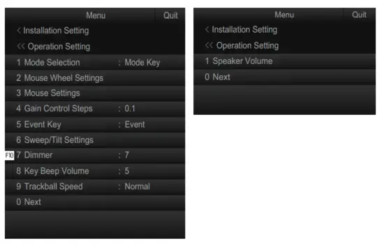
| Menu item | Remarks |
| [1 Mode Selection] | Determines how display modes are selected.
|
| [2 Mouse Wheel Settings] | Sets items related to scrollwheel operation. Left-click this item to show its setting menu.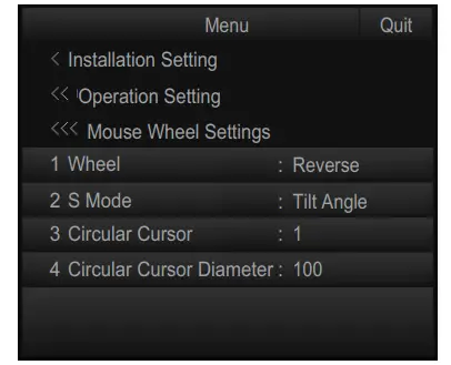
|
| Menu Item | Remarks |
| [3 Mouse Settings] | Select the function to be assigned to the left and right button on the trackball from [Fish Marti]. [Fish Mark2], [Event Maki], [Event Mark2). [Estimate Mark]) a [Estimate Mark2).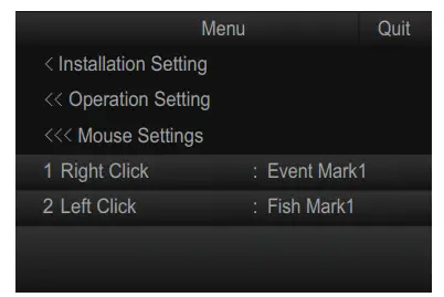 |
| [4 Gain Control Steps) | Sets the amount of change with each interval on the GAIN knob (setting range: [0.1). [0.2). [0.5)). |
| [5 Event Key) | Sets the key to use to enter an own ship position mark. [Event) or [Shoot]. |
| [6 Sweep/Tilt Settings] | Sets the sector and tilt angle. Select this item to show its setting menu.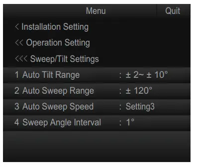
|
| [7 Dimmer] | Adjusts the illumination of the control unit operation panel (setting range: 0 to 15). |
| [8 Key Beep Volume] | Sets the volume of the beep which sounds for key operation (setting range: 0 to 7). |
| [9 Trackball Speed) | Sets the tracking speed of the trackball. [Slow). Normal). [Fast]. |
| [1 Speaker Volume] | Sets the volume of the internal speaker. Drag the volume bar up to increase. or down to decrease, the volume. To silence the audio, click the check-box at [Mute) to show a check-mark. |
3.17.4 [Motion Sensor] menu
You can offset the pitch and roll angle for the motion sensor on the [Motion Sensor] menu. To display this menu, select [3 Motion Sensor] from the [Installation Setting] menu.
Note: This setting is only required if the motion sensor is installed separately from the hull unit.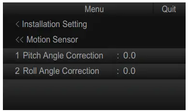
| Menu item | Remarks |
| [1 Pitch Angle Correction] | Offsets the pitch angle at the motion sensor. |
| [2 Roll Angle Correction] | Offsets the roll angle at the motion sensor. |
3.17.5 [Hull Unit Setting] menu
You can setup information about the hull unit on the [Hull Unit Setting] menu. To display this menu, select [4 Hull Unit Setting] from the [Installation Setting] menu.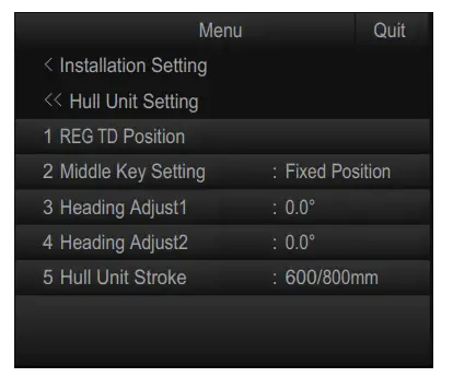
| Menu item | Remarks |
| [1 REG TD Position] | Registers the transducer position. For details, see section 3.3. |
| [2 Middle Key Setting] | Sets the operation when the left
|
| [3 Heading Adjust1] | Offsets the transducer heading. For details, see section 3.5. |
| [4 Heading Adjust2] | Offsets the motion sensor heading. For details, see section 3.5. |
| [5 Hull Unit Stroke] | Selects the stoke (length) of the hull unit ([600/800 mm] or [1100 mm]). |
3.17.6 [Interface Setting] menu
Set the transmission rate for the NMEA ports on the [Interface Setting] menu. To display this menu, select [5 Interface Setting] from the [Installation Setting] menu.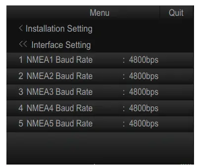
| Menu item | Remarks |
| [1 NMEA1 Baud Rate] | Set the transmission rate for each NMEA port (setting range: [4800bps], [9600bps], [19200bps], [38400bps]). |
| [2 NMEA2 Baud Rate] | |
| [3 NMEA3 Baud Rate] | |
| [4 NMEA4 Baud Rate] | |
| [5 NMEA5 Baud Rate] |
3.17.7 [External Data] menu
Select the input format for external data on the [External Data] menu. To display this menu, select [6 External Data] from the [Installation Setting] menu.
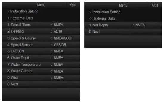
| Menu item | Remarks |
| [1 Date & Time] | Sets the input format for date and time data (setting range: [Disable], [NMEA]). |
| [2 Heading] | Sets the input format for heading data (setting range: [Disable], [AD1 0], [NMEA]). |
| [3 Speed & Course] | Sets the input format for ship’s speed and course data (setting range: [Disable], [NMEA (SOG)], [NMEA (STW)]). |
| [4 Speed Sensor] | Sets the type of device which is used as the speed and course data source (setting range: [Disable], [GPS/DR], [Doppler/DR]). |
| [5 LAT/LON] | Sets the input format for position data (setting range: [Disable], [NMEA]). |
| [6 Water Depth] | Sets the input format for water depth (setting range: [Disable], [NMEA]). |
| [7 Water Temperature] | Sets the input format for water temperature (setting range: [Disable], [NMEA]). |
| Menu item | Remarks |
| [8 Water Current] | Sets the input format for water current (setting range: [Disable], [NMEA]). |
| [9 Wind] | Sets the input format for wind data (setting range: [Disable], [NMEA]). |
| [1 Net Depth] | Sets the input format for net depth data (setting range: [Disable], [NMEA]). |
3.17.8 [Own Ship Data] menu
Enter the own ship’s information on the [Own Ship Data] menu. To display this menu, select [7 Own Ship Data] from the [Installation Setting] menu.
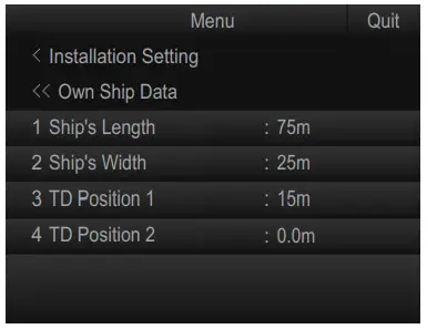
| Menu item | Remarks |
| [1 Ship’s Length] | Sets the length of the ship. |
| [2 Ship’s Width] | Sets the width of the ship at its widest point. |
| [3 TD Position 1] | Sets the distance from the transducer to the bow. |
| [4 TD Position 2] | Sets the distance from the transducer to keel. Set a positive value for starboard installations, a negative value for port installations. |
3.17.9 [Initialization] menu
You can change the language setting and restore the factory default on the [Initialization] menu. To display this menu, select [8 Initialization] from the [Installation Setting] menu.
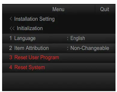
Note: When you select [8 Initialization] from the [Installation Setting] menu, the following confirmation message appears. Select [OK] to open the [Initialization] menu.
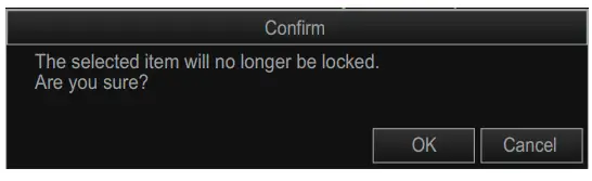
| Menu item | Remarks |
| [1 Language] | Sets the language to use. |
| [2 Item Attribution] | When a protected menu item (in red) is clicked, you are asked if you want to display a confirmation message to enable settings changes. However, the following menu items display the confirmation message regardless of this setting.
|
| [3 Reset User Program] | Restores all user programs to their default settings. When [3 Reset User Program] is selected, the following message appears. Select [Yes] to restore the default settings. |
| [4 Reset System] | Restore all settings other than the following menu items to default settings:
When [4 Reset System] is selected, the following message appears. Select [Yes] to restore factory settings. After selecting [Yes], the message “Press the power key to restart.” appears. Restart the system to apply the settings. |
APPENDIX 1 JIS CABLE GUIDE
Cables listed in the manual are usually shown as Japanese Industrial Standard (JIS). Use the following guide to locate an equivalent cable locally.
JIS cable names may have up to 6 alphabetical characters, followed by a dash and a numerical value (example: DPYC-2.5).
For core types D and T, the numerical designation indicates the cross-sectional Area (mm²) of the core wire(s) in the cable.
For core types M and TT, the numerical designation indicates the number of core wires in the cable.
- Core Type
D: Double core power line
T: Triple core power line
M: Multi core
TT: Twisted pair communications
(1Q=quad cable) - Insulation Type
P: Ethylene Propylene Rubber - Sheath Type
Ethylene Propylene Rubber
Y: PVC (Vinyl) - Armor Type
C: Steel - Sheath Type
Y: Anticorrosive vinyl sheath - Shielding Type
SLA: All cores in one shield, plastic tape with w/aluminum tape
-SLA: Individually shielded cores, plastic tape with w/aluminum tape
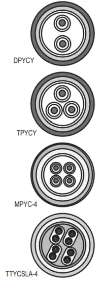
![]()
The following reference table lists give the measurements of JIS cables commonly used with Furuno products:

APPENDIX 2 INSTALLATION CHECKLIST
After completing the installation, perform the following checks:
| Checkpoint | Reference | Result | |
| Hardware installation check | |||
| Sonar oil | The dome is filled with sonar oil. | section 1.9 | ❑ |
| 0-ring in the retraction tank flange | 0-ring, gasket*, and insulation packing* are attached to the retraction tank flange. *: Attached only when the attachment kit or attachment flange is used. | section 1.2.5/ section 1.10.1/ section 1.10.2 | ❑ |
| Tank guide position at transducer full protrusion | Lower the transducer until fully protruded, then confirm that the rollers on the tank guide are not projected from the retraction tank. Tank guide must be positioned 30 mm inside from the bottom of the retraction tank. | – | ❑ |
| Bow mark direction of the transducer | Confirm that the bow mark on the transducer faces the bow direction. | section 1.2.9 | ❑ |
| Soundome assembly operation check | Check the LEDs in the control box to perform the soundhole assembly operation check. | section 1.2.10 | ❑ |
| Input voltage toggle switch on the transceiver unit | Input voltage toggle switches on the transceiver unit are changed correctly, depending on the input voltage. | section 2.3.3 | ❑ |
| Vibration and sound while raising/lowering the transducer | Confirm that abnormal vibration or noise is not generated from the hull unit while raising/lowering the transducer. | – | ❑ |
| Software setting check | |||
| Language setting | The language in which the menus and indications is changed as necessary. | section 3.2 | ❑ |
| Year/Month of oil change | Register the year and month of the sonar oil change. | section 3.16 | ❑ |
| Transducer position registration | The transducer position registration is completed. | section 3.3 | ❑ |
| Turn the transmission on | Change the transmission status from [OFF] to [ON]. | section 3.4 | ❑ |
| Heading Correction | Adjust the heading so an echo that is dead ahead appears dead ahead on the display. | section 3.5 | ❑ |
| Direction offset of the motion sensor | Offset the direction difference between the [Reference Direction] mark on the motion sensor and bow direction. | section 3.5 | ❑ |
| Stroke setting | Select 800 mm or 1100 mm according to the stroke (length) of your hull unit. | section 3.6 | ❑ |
| External data setting | Set the baud rate for the NMEA2000 port and select the input format for external data. | section 3.17.6/ section 3.17.7 | ❑ |
| System time setting | Set the system time and time zone. | section 3.12 | ❑ |
| Save ship’s original setting | Save all menu settings in the internal memory as necessary. | section 3.10 | ❑ |
| Checkpoint | Reference | Result | |
| Display setting for the numeric/graphic data display | Change the display setting for the numeric/ graphic data display as appropriate. | Operator’s manual | |
| ❑ | |||
| Function key setting | Assign the function to the function keys as necessary. | Operator’s manual | |
| ❑ | |||
| Preset the horizontal mode ranges | Preset the horizontal mode ranges as selected with the RANGE control as necessary. | Operator’s manual | |
| ❑ | |||


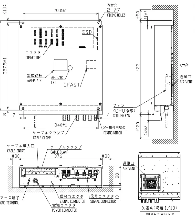
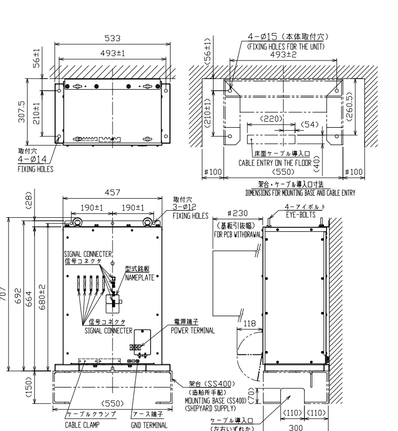
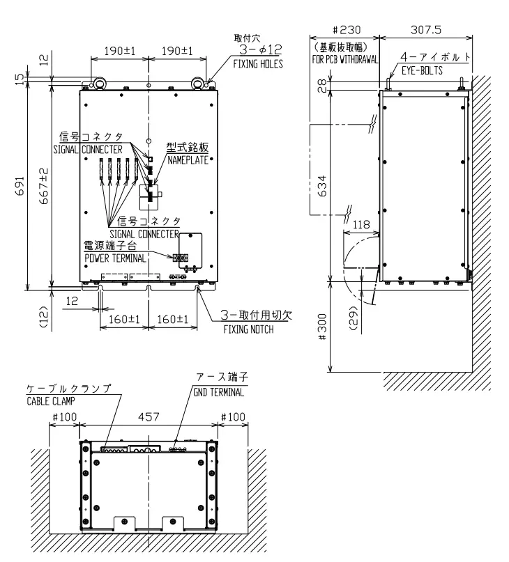
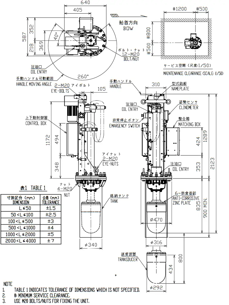
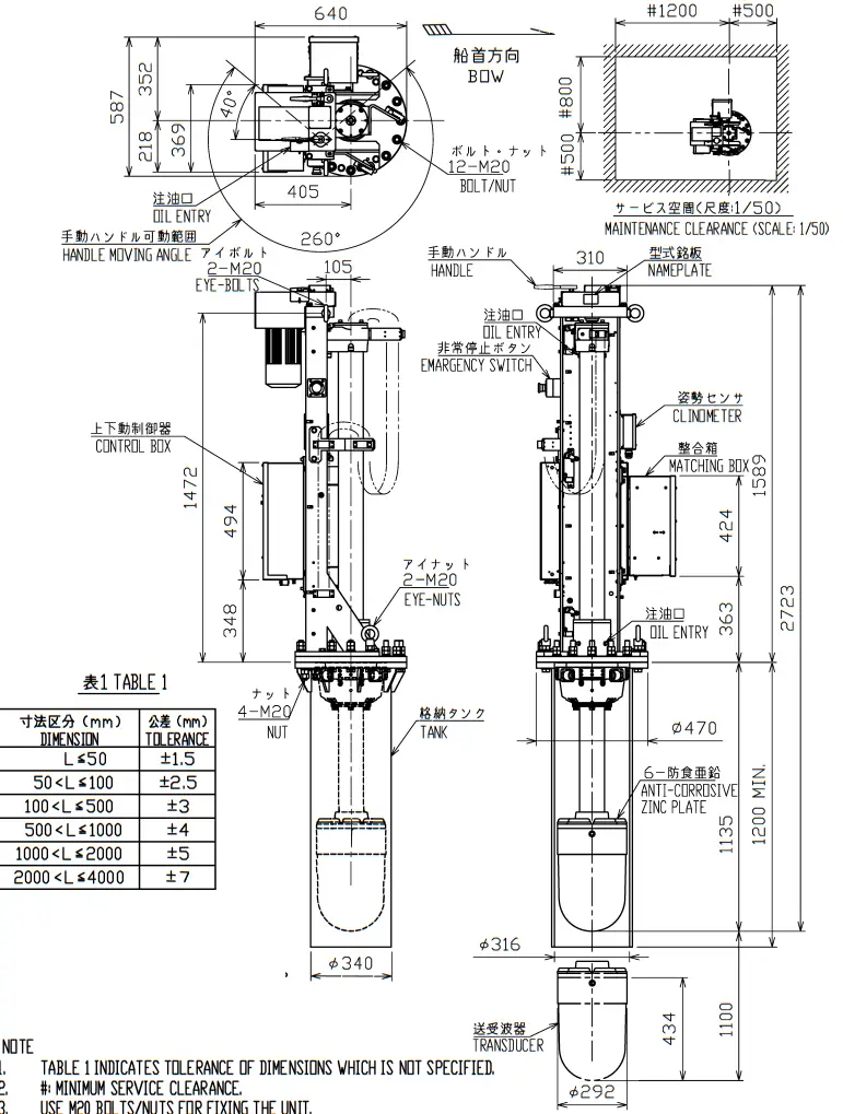
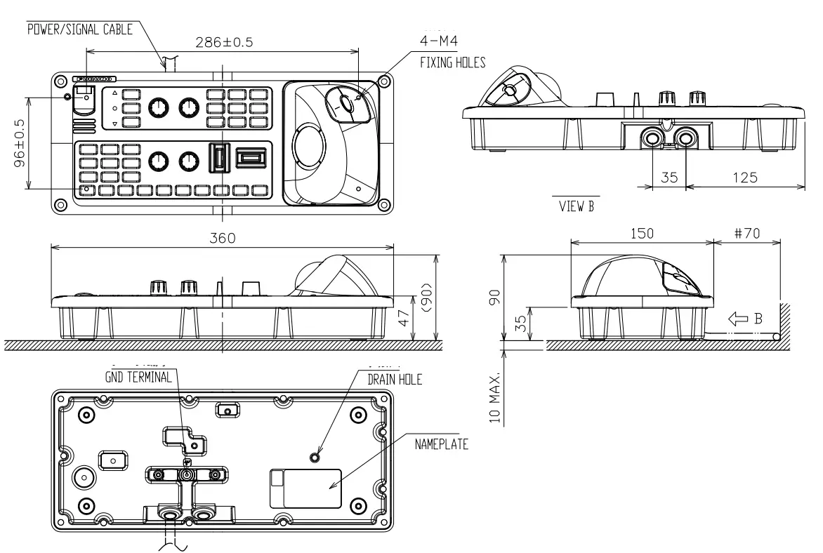
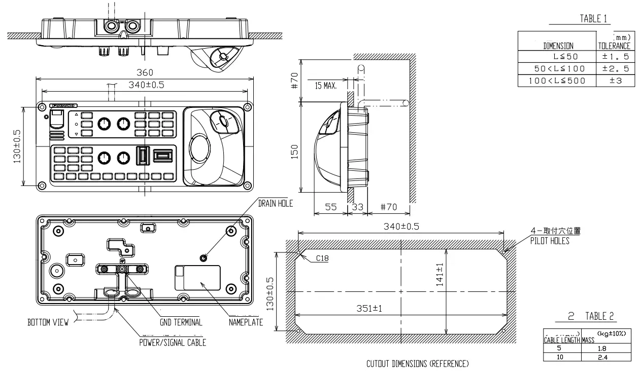
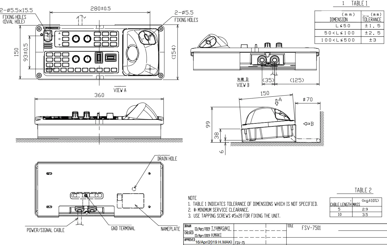
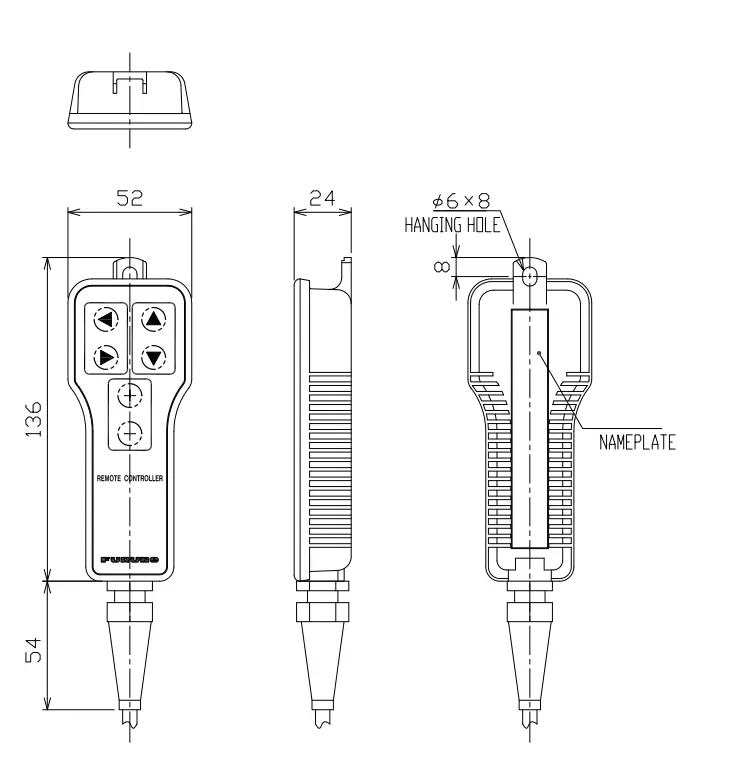
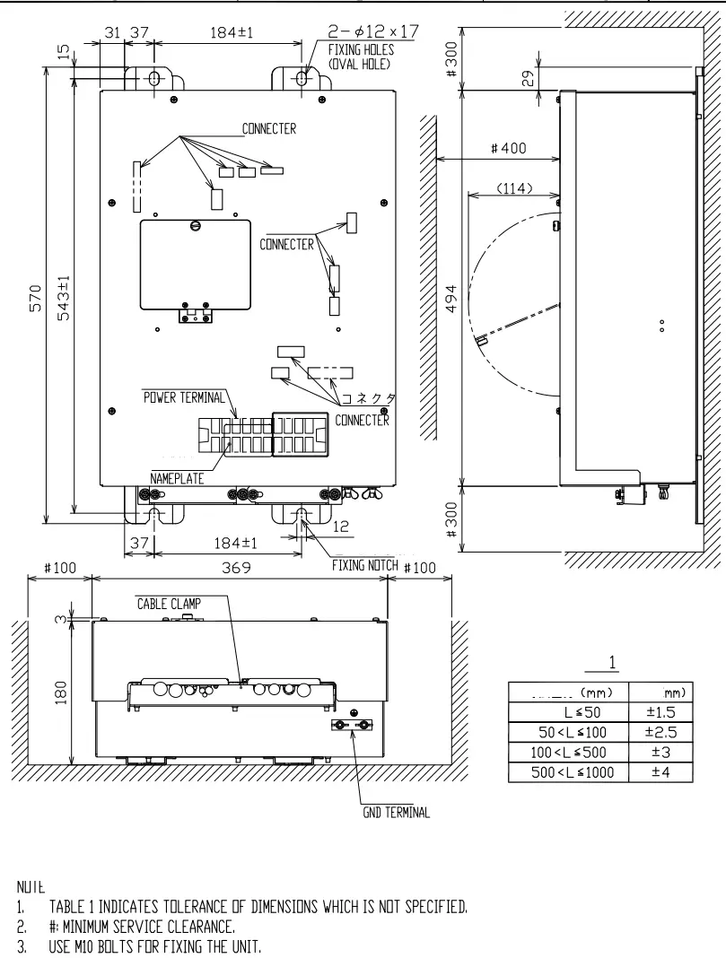
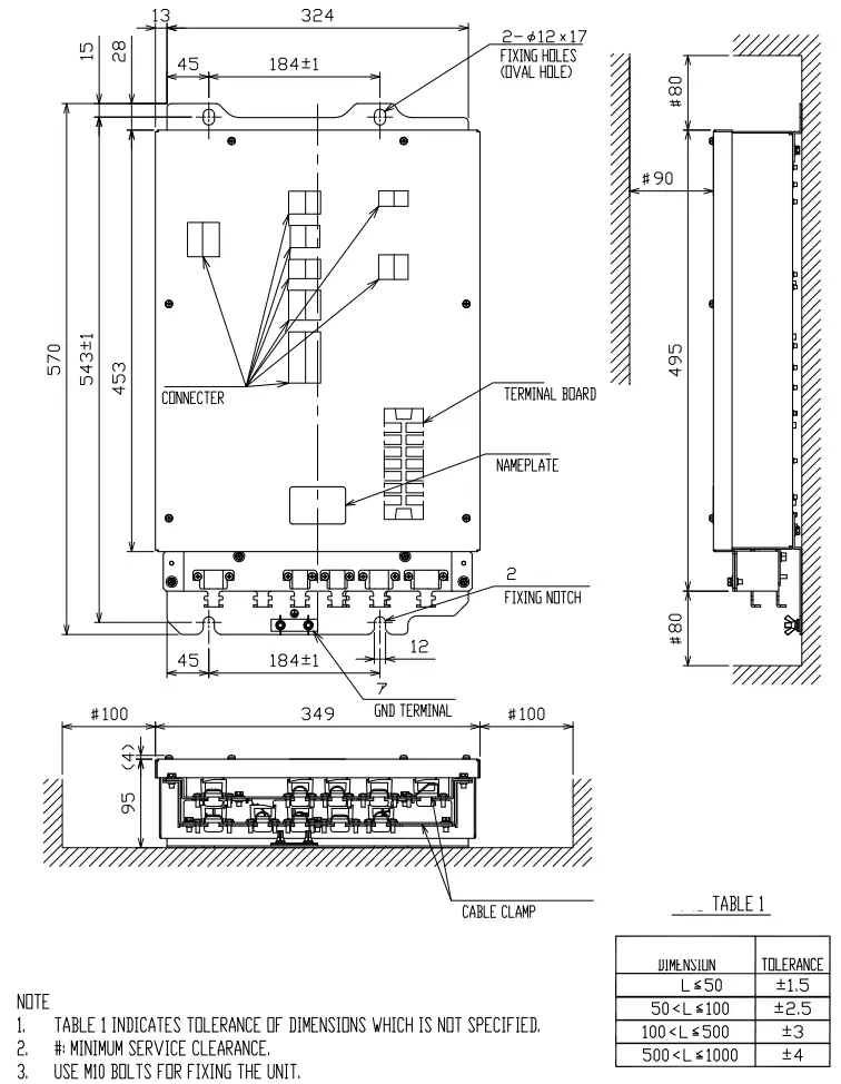
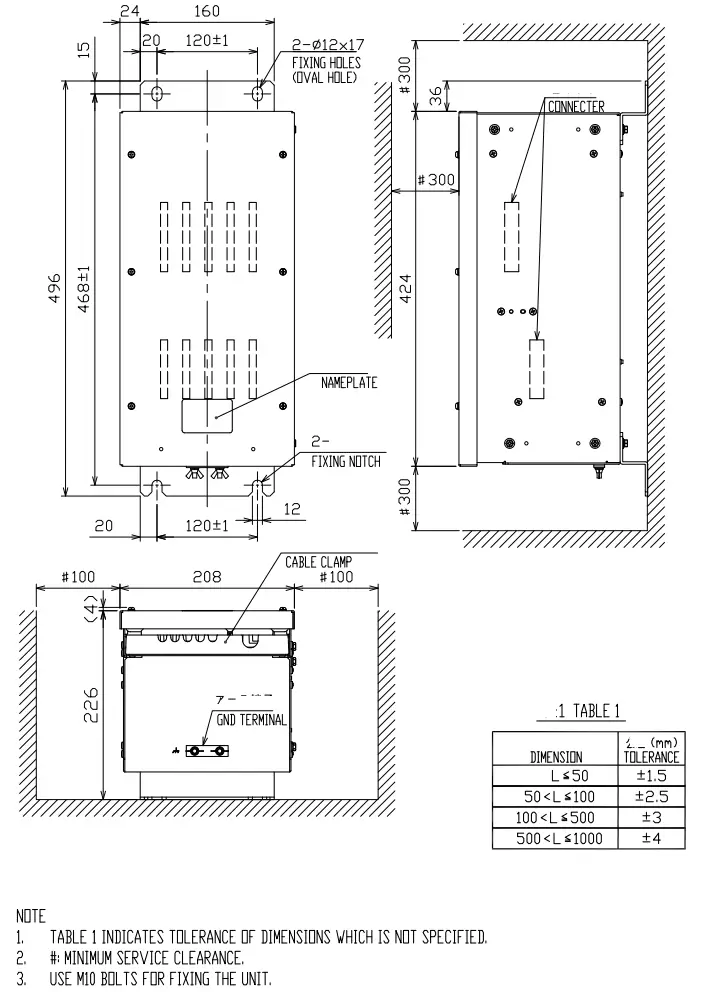
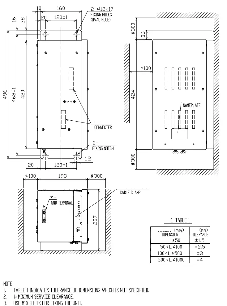
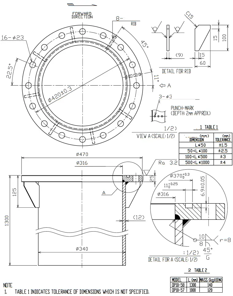
|
|
|
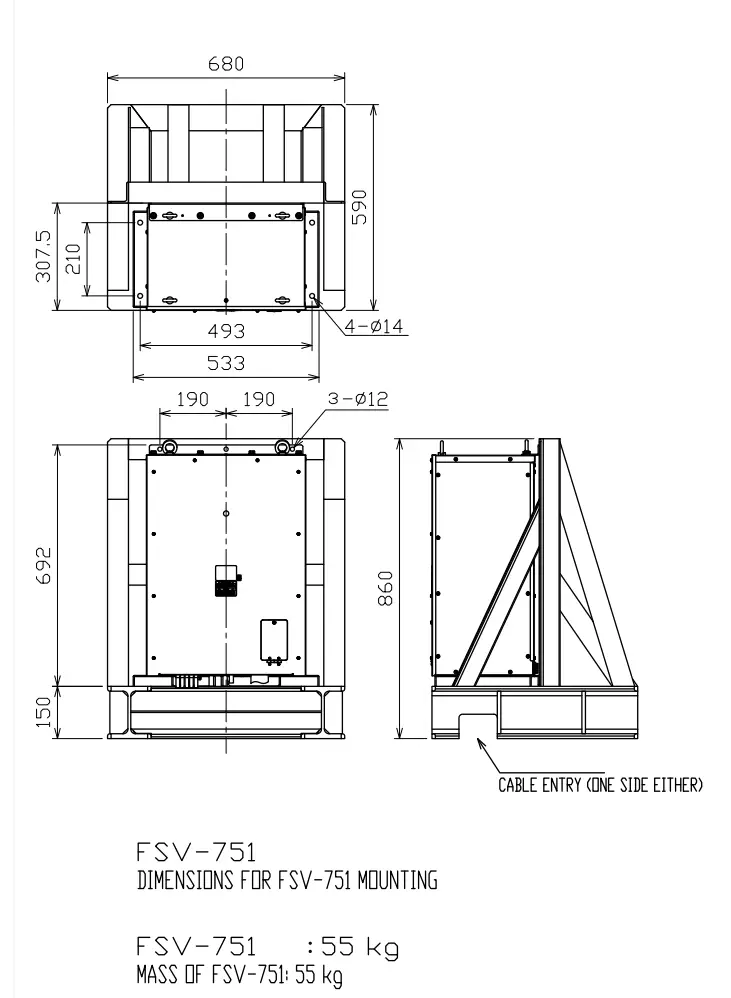
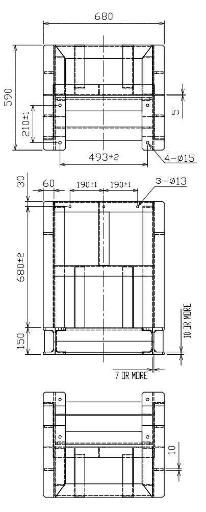
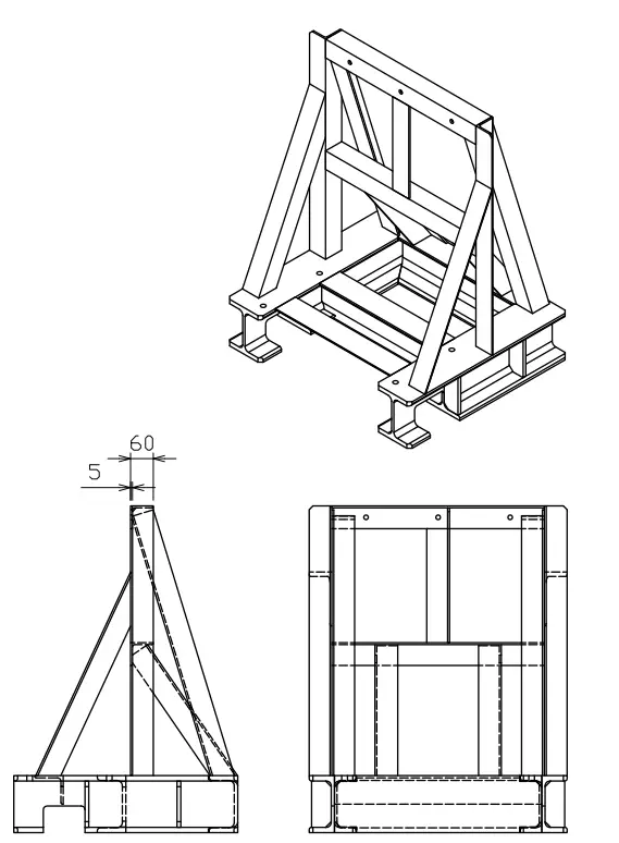
MOUNTING BASE SAMPLE (SHIPYARD SUPPLY) (DIMENSIONS ARE DECIDED BY SHIPYARD) (FOR FLOOR MOUNT; REFER TO ANOTHER DRAWING FOR BULKHEAD MOUNT) L-ANGLE SIZE (UPPER): 60 X 60 (t5) OR MORE. BASE-ANGLE (STEEL I-BEAM) SIZE (LOWER): 150×150 (W6x15-in) OR MORE
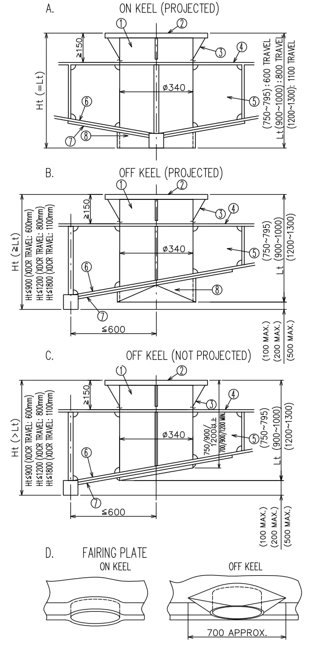
INSTALLATION METHOD OF RETRACTION TANK
- Install tank to hull plate with fillet welding taking the following points into account; * Flange face is exactly horizontal at normal ship’s trim. * Bow mark on side of the flange should be faced deadly ahead. * Allow height of flange face from keel bottom “Ht” mentioned in the drawings, otherwise transducer beam is blocked by the keel when the transducer is fully lowered. * Tank’s length “Lt” should be less than Ht”. If not so, the bottom end of the tank is placed below keel level. “Lt” is also limited as shown in the drawings so that the transducer can be fully retracted in the tank. (The tank is supplied with 1000/1300 mm long as standard.
- Fit doubling plate of outer dia. 0700 around the tank on the hull plate. Fit fairing plate reffering to the drawing ‘D’ for installation methods A and ‘B’. Use same material and thickness of doubling and fairing plate as hull plate.
- Weld the tank into the bulkhead ()around the tank.
- Allow a clearance of more than 150 mm below the flange face for easy bolting. Sink the inner hull-plate as shown in drawing ‘B’ for a high inner hull plate.
TABLE 1 RETRACTION TANK
| VA | 21-0-9 | 9)91 |
| OP10-59 | 600 mm | 900 mm |
| OP10-57 | 800 mm | 1000 mm |
| OP10-58 | 1100 mm | 1300 mm |
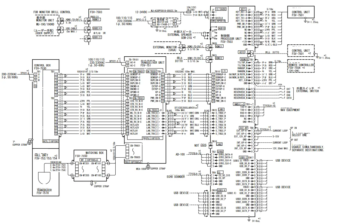
Note
* 1: SHIPYARD SUPPLY
*2: OPTION.
*3: FSV -752 IS AVAILABLE IN JAPAN ONLY.
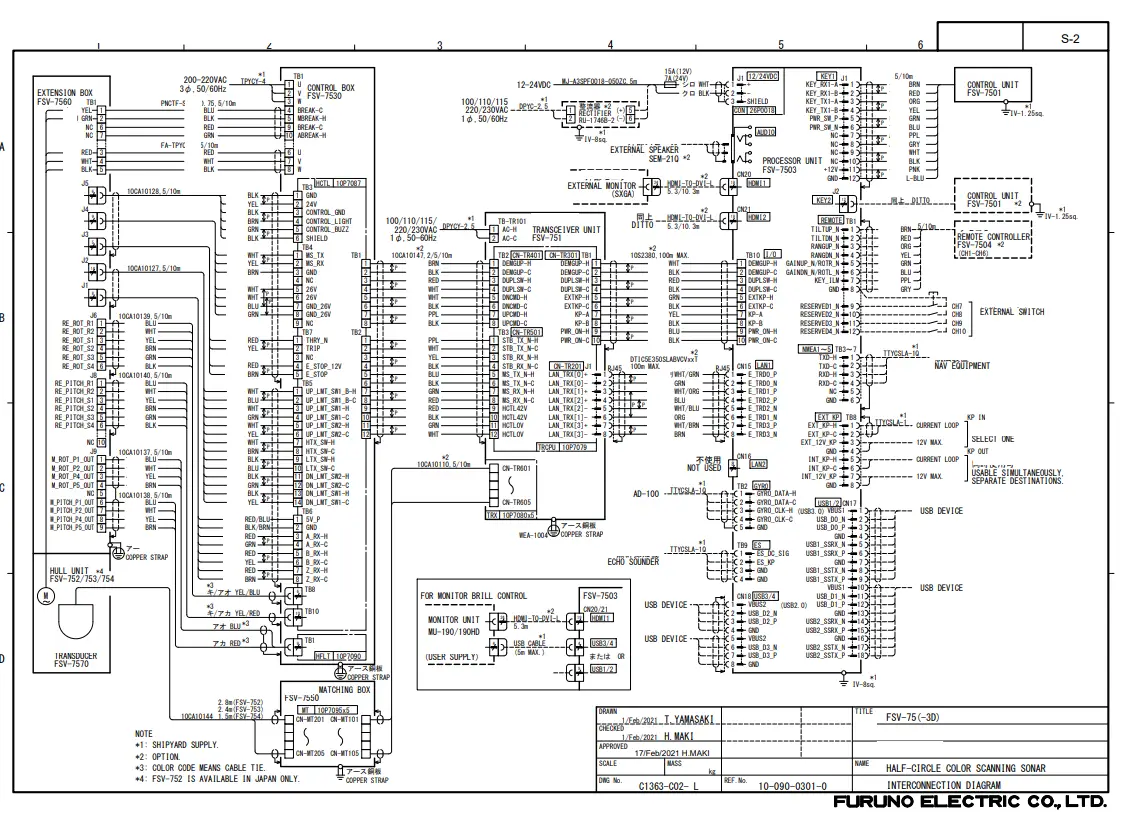
![]() FURUNO ELECTRIC CO., LTD
FURUNO ELECTRIC CO., LTD
www.furuno.com
All brand and product names are trademarks, registered trademarks, or service marks of their respective holders.![]()
( Elemental Chlorine Free)
The paper used in this manual is elemental chlorine free.
9-52 Ashihara-cho,
Nishinomiya, 662-8580, JAPAN
All rights reserved.
Printed in Japan
Pub. No. IME-13630-F
(REFU ) FSV-75
・FURUNO Authorized Distributor/Dealer
A : APR 2019.
F : MAR . 09, 2021