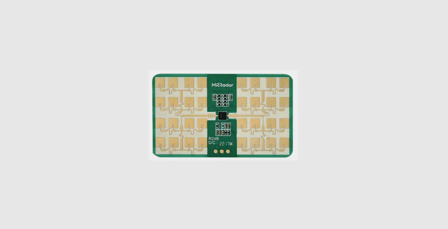
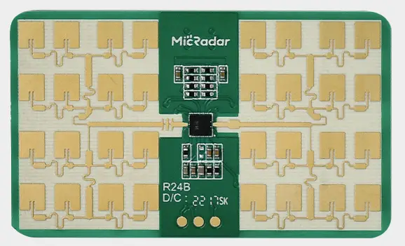
seed studio MR24BSD1 24GHz mmWave Module
Overview
This document focuses on the use of the radar, the issues that need to be addressed at each stage to minimize design costs and increase product stability and improve the efficiency of project completion. From hardware circuit reference design, radar antenna and housing layout requirements, how to differentiate between interference and multi-functional standard UART protocol outputs.
The radar is a self-contained space sensing sensor, consisting of RF antenna, radar chip and high speed main frequency MCU together with a module that relies on a stable and flexible superior algorithm architecture core to solve the user’s various scenario detection needs, which can be equipped with a host computer or host computer to flexibly output detection status and data, meeting several groups of GPIOs for custom development.
Principle of operation 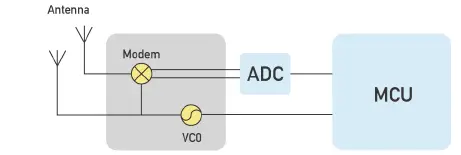
The radar transmits a millimetre wave signal in the 24G band, the measured target reflects the electromagnetic wave signal and demodulates the transmitted signal, which is then amplified, filtered and processed by ADC to obtain the echo demodulated signal data. The amplitude, frequency and phase of the echo signal are decoded in the MCU unit, which ultimately enables the measurement of target parameters (breathing, movement, micro-motion, etc.) and scene evaluation.
Hardware Design Considerations
The radar needs to have a rated supply voltage of 4.9 – 6V and a rated current requirement of 200mA or more input under normal operating conditions. The power supply must be designed for a supply ripple of ≤ 100mv.
The power supply can be designed with the following circuit in mind 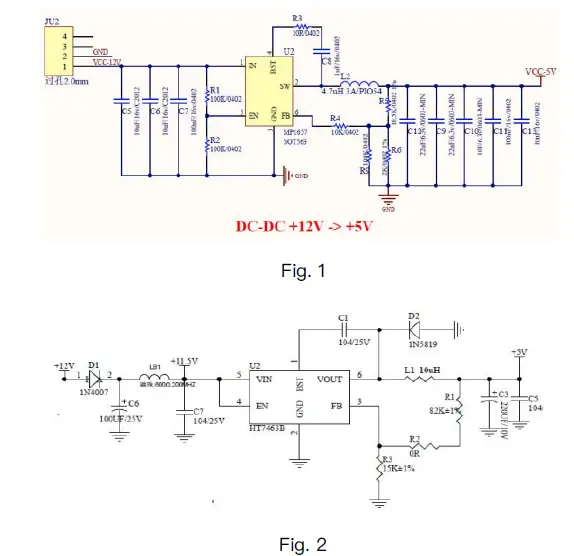
using the wiring diagram 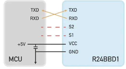
Fig. 3 Schematic diagram of the radar module and peripheral connections
Antenna and housing layout requirements
PCBA: the radar needs to be kept ≥ 1mm higher than the other components Housing construction: need to maintain a distance of 2 – 5mm between the radar antenna face and the housing face
Housing detection surface: non-metallic housing, needs to be flat and straight to avoid curved surfaces which can affect the performance of the entire swept surface area.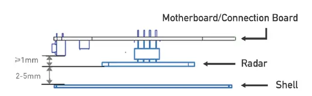
Fig. 4 Schematic diagram of the radar module and peripheral connections
Static Protection
Radar products have electrostatic sensitive circuitry and are susceptible to electrostatic hazards, therefore they need to be adequately protected from static electricity during transport, storage, work and handling. When handling radar sensors, please wear anti-static gloves if possible.
Functional disturbances
Unoccupied state, abnormal output occupied
In normal conditions, the radar will accurately determine the presence of a sitting or sleeping body and output information on falls, breathing, vital signs etc.
- Radar scanning area is large, doorway, boarded wall next door movement is detected
Adjustment method: reduce radar sensitivity, radar provides scene setting B. Radar underneath is facing a running air conditioner or fan Adjustment: adjust the radar position so that it is not directly in front of the air conditioner or fan - Shifting objects caused by air conditioning winds
Adjustment method: cotton, non-metallic objects will not cause false alarms, metal objects need to be fixed - The radar is not fixed, vibration causes false alarms
Avoid supporting shaking and vibration - Occasional moving objects such as pets, birds, etc.
As the radar measures micro-movements, the sensitivity is very high and this interference cannot be excluded - Power supply interference, resulting in occasional false alarms
Try to keep the power supply current stable and reduce ripple
Manned status, abnormal output unoccupied
Radar determines the presence of a human body by sending and receiving electromagnetic waves. The closer you are to the radar, the more accurate it is.
- Human body out of radar range
Radar scanning range with adjustment of mounting angle. Radar measurement range, in different environments with different electromagnetic wave reflection areas, the scanning area will vary slightly. - False output due to metal occlusion
Excessively thick desks and chairs, metal seats. It will block the electromagnetic wave penetration and cause misinterpretation. C. Differences in scanning angles
The radar does not scan the torso area. This can lead to false positives. D. Radar sensitivity is too low
The radar offers parameter adjustment to increase sensitivity for improvement.
Functions in detail
Function point descriptions
| Functions | Status change time/function explanation |
| DP1: occupied/unoccupied | No one to occupied, report within 0.5s Manned to unoccupied, no status output in 1- 2 minutes or so |
| DP2: Some people are stationary / Some people are active | Static dynamic switching, reporting within 0.5 seconds |
| DP3: Someone close to the device / someone moving away from the device / someone moving without direction | Status output once every 2 seconds |
| Functions | Status change time/function explanation |
| DP4: Body movement amplitude parameter 0 – 100 | Data output once every 5 seconds Reference (description of output of body motion amplitude parameters) |
| DP5: Sensitivity setting 1 – 10 steps | Default scene mode, adapted to 10 positions of adjustment |
| DP6: Scene modes (bed, bathroom, hotel, bedroom, office, default mode) | Adapted to different scenarios according to the size of the area |
| DP7: No false alarm confirmation prompt | |
| DP8: Sleep parameter switch | Off by default, sleep function only works when on |
| DP9: Bed entry/exit | Output status in 3S clock |
| DP10: Number of bed entries/exits | Count the number of times you enter/leave bed in a day |
| DP11: Stationary dwell alarms | Outputs in three states, once every 10 minutes |
| DP12: Length of Sobriety | |
| DP13: Length of light sleep | |
| DP14: Length of deep sleep | |
| DP15: Breathing rate | Normal number of breaths can be tested |
|
DP16: Breathing rate detection signal | If there are factors such as distance, range and other effects, output breath-holding abnormalities, good signals, abnormal movements, abnormal states of shortness of breath |
| DP17: Sleep scoring (optional, users can rate according to their own way) | Combined day’s sleep rating |
Description of the output of the body motion amplitude parameter
| Body movement amplitude parameters | ||
| 0% | None | Environmental unmanned |
| 1% | Stationary (sleep) | Only breathing without body movement |
| 2% – 30% | Micro-Movements | Only minor head or limb movements Movement |
| 31% – 60% | Walking/fast body movements | Slower body movements |
| 61% – 100% | Running/close range big moves | Rapid body movement |
Description of the agreement
This protocol is used to communicate between a 24G millimeter wave sleep detection radar and a host computer.
This protocol outlines the radar workflow, provides a brief introduction to the interface protocol component architecture and gives the control commands and data required for the operation of the relevant radar, with the serial communication defined as follows.
- Interface level: TTL
- Baud rate: 9600bps
- Stop bits: 1
- Data bits: 8
- Parity: None
Communication commands and parameter definitions
Definition and description of the frame structure
- Frame structure definition
- Description of the frame structure
- Start code: 1 Byte, fixed to 0X55.
- Data length: 2 Byte, low byte before, high byte after.
Length = Data Length + Function Code + Address Code 1 + Address Code 2 + Data + Checksum. - Function code: 1 Byte
- Read command: 0X01 Write command: 0X02
Passive report command: 0X03
Active report command: 0X04
- Address code: Address code 1
indicates the function classification, address code 2 indicates the specific function.
See the description of address assignment and data information. - Data: n Byte
- Checksum: 2 Byte, low byte before, high byte after.
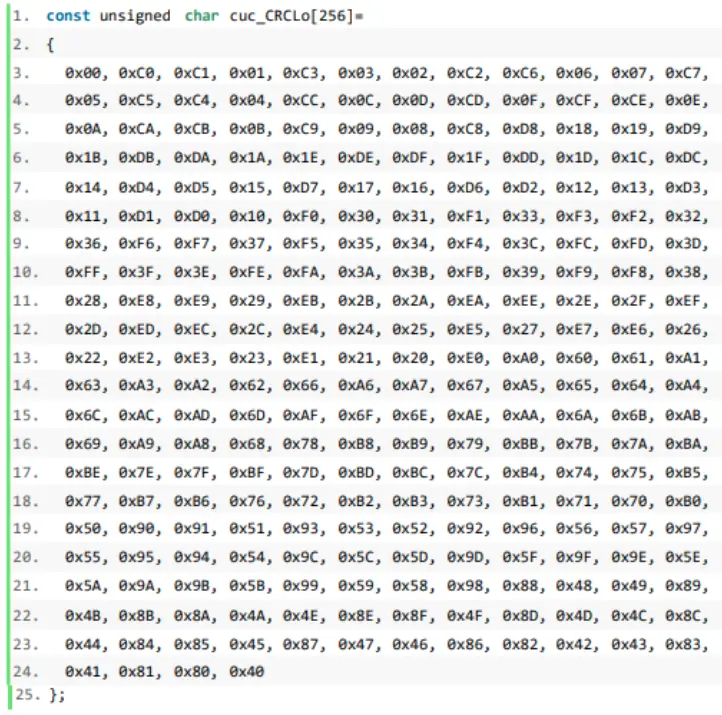
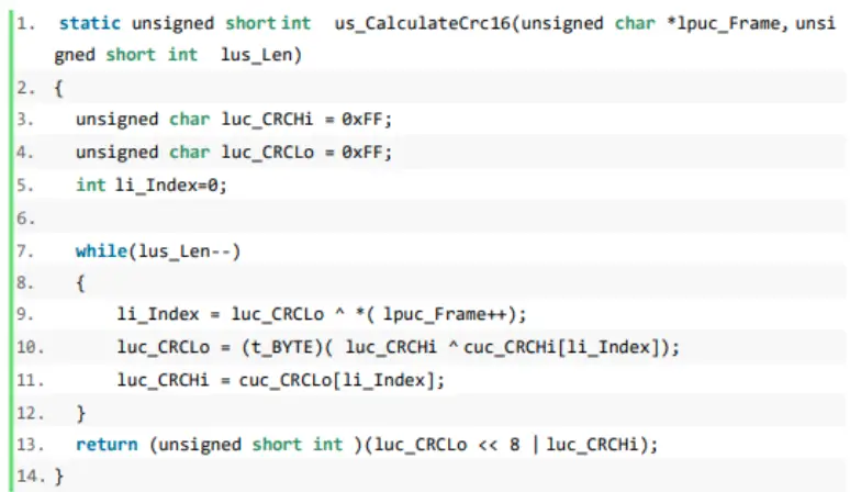
CRC16 checksum is used, see Appendix 1 for reference code.
Description of address assignment and data information
| 24G Bio-aware radar interface content | |||||
| Function Code | Address code 1 | Address code 2 | Data | Notes | |
| 1 | Device ID 0X01 | ||||
| 2 | Marking | Software version 0x02 | |||
| search | |||||
| 3 | 0x01 | Hardware version 0x03 | |||
| 4 | Protocol version 0x04 | ||||
| 5 | Radar Information | Environmental status 0X05 | |||
| Search | |||||
| 6 | Read command | 0x03 | Signs parameters 0x06 | ||
| 0x01 | |||||
| 7 | Threshold gear 0x0C | ||||
| System | |||||
| 8 | parameter | Scene setting 0x10 | |||
| search | |||||
| 0x04 | Forced into unoccupied | ||||
| gear 0X12 | |||||
| Other | Enquiry | ||||
| 9 | information enquiries | Sleep detection parameter switch 0X0D | Current sleep detection | ||
| 0X05 | switch status | ||||
| 24G Bio-aware radar interface content | |||||
|
1 |
copy order 0x02 |
System parameters 0x04 |
Threshold gear 0x0C |
Enumeration range1~10 | Corresponding to1 2 3 4 5 6 7 8 9 10 gears (default 7) The higher the gear, the more sensitive it is |
| 2 |
Scene setting 0x10 | Default mode 0x00 | |||
| 3 | Area detection (top loading) 0x01 | ||||
| 4 | Bathroom (top mounted) 0x02 | ||||
| 5 | Bedroom (top loading) 0x03 | ||||
| 6 | Living room (top mounted) 0x04 | ||||
| 7 | Office (top loading) 0x05 | ||||
| 8 | Hotel (top loading) 0x06 | ||||
|
Forced into unoccupied gear 0X12 | No forced access to the unoccupied function 0X00 | ||||
| 10s 0X01 | |||||
| 30s 0X02 | |||||
| 1min 0X03 | |||||
| 2min 0X04 | |||||
| 5min 0X05 | |||||
| 10min 0X06 | |||||
| 30min 0X07 | |||||
| 60min 0X08 | |||||
| 24G Bio-aware radar interface content | |||||
| 9 | Other functions 0X05 | Reboot 0X04 | |||
| 10 | Sleep function switch 0x0D | Off 0x00 | |||
| On 0x01 | |||||
| Start OTA upgrade 0X08 | 4byte Integer data (firmware package size)+ nbyte (software version number) | ||||
| Upgrade package transfer 0X09 | Packet Offset (4byte) + Packet (1024byte) | ||||
| End of upgrade information 0X0A | Fixed characters 0X0F | ||||
| 24G Bio-aware radar interface content | ||||||
| 1 | Passive | Device ID 0x01 | 12 Byte data | |||
| reporting of orders | Reporting module identification 0X01 | |||||
| 2 | Software version 0x02 | 10 Byte data | ||||
| 3 | Hardware version 0x03 | 8 Byte data | ||||
| 4 | 0x03 | Protocol version 0x04 | 8 Byte data | |||
| 24G Bio-aware radar interface content | |||||
| 1 |
Passive reporting of orders 0x03 | Upload Radar Info 0x03 | Environment status 0x05 | Nobody 00 FF FF | |
| 2 | Static 01 00 FF | ||||
| 3 | Movement 01 01 01 | ||||
| 4 | Signs parameters 0x06 | 4 Byte Float data (see Appendix 2) | |||
| 5 |
Reporting system parameters 0X04 | Threshold gear 0X0C | Current gear value (0X01~0X0a) | ||
| 6 |
Scene setting 0x10 | Default mode 0x00 | |||
| 7 | Area detection (top loading) 0x01 | ||||
| 8 | Bathroom (top mounted) 0x02 | ||||
| 9 | Bedroom (top loading) 0x03 | ||||
| 10 | Living room (top mounted) 0x04 | ||||
| 11 | Office (top loading) 0x05 | ||||
| 12 | Hotel (top loading) 0x06 | ||||
|
Forced into unoccupied gear 0X12 | No forced access to the unoccupied function 0X00 | ||||
| 10s 0X01 | |||||
| 30s 0X02 | |||||
| 1min 0X03 | |||||
| 2min 0X04 | |||||
| 5min 0X05 | |||||
| 10min 0X06 | |||||
| 30min 0X07 | |||||
| 60min 0X08 | |||||
| 13 |
Other functions 0X05 | Sleep function switch 0x0D | Off 0x00 | ||
| On 0x01 | |||||
| 14 | Start OTA upgrade 0X08 | Failed 0X00 | |||
| 15 | Success 0X01 | ||||
| 16 | Upgrade package transfer 0X09 | Fixed characters 0X0F |
| 24G Bio-aware radar interface content | ||||||
| 1 |
Proactive reporting of commands 0X04 |
Report radar information 0x03 |
Environment status 0x05 | Unoccupied 00 FF FF | ||
| 2 | Someone is stationary 01 00 FF | |||||
| 3 | U Some people exercise 01 01 01 | |||||
| 4 | Motor signs parameters 0X06 | 4Byte Float data | ||||
|
5 |
Approaching away state 0x07 | Fixed characters 0x01 0x01 | None 0x01 | |||
| Approach 0x02 | ||||||
| Far away 0x03 | ||||||
| 6 | Report other information 0X05 |
Heartbeat Pack 0X01 | Unoccupied 00 FF FF | |||
| 7 | Someone is stationary 01 00 FF | |||||
| 8 | Some people exercise 01 01 01 | |||||
| 24G Bio-aware radar interface content | |||||
|
9 | Abnormal reset 0X02 | 0X0F | When the radar is restarted or re- powered, an abnormal reset command is reported before the initialisation process begins and a successful initialisation command is reported. | ||
|
Initialisation successful 0X0A |
0X0F | ||||
| This means that the radar has been initialized successfully. | |||||
| Start of normal operations. | |||||
| 24G Bio-aware radar interface content | |||||
| 1 | Sleeping | Breathing rate 0x01 | 1Byte integer data | ||
| radar | Breathing | Breath-holding | |||
| data reporting 0x05 | parameters 0x01 | Detection signal 0x04 | abnormality 0x01 | ||
| No 0X02 | |||||
| Normal 0x00 | |||||
| 24G Bio-aware radar interface content | |||||
|
Movement abnormalities 0X04 | When large movements of the person occur, abnormal movements are indicated, informing the user that large movements may affect the radar’s detection of breathing | ||||
| Shortness of breath abnormal 0X05 | |||||
| 2 |
Scenario assessment 0x03 | In/out of bed 0x07 | Out of bed 0X00 | ||
| 3 | In bed 0X01 | ||||
| None 0x02 | Sleep switch off shows none | ||||
| 4 |
Sleep state assessment | Awake 0x00 | |||
| 5 | Light sleep 0x01 | ||||
| 6 | Deep sleep 0x02 | ||||
| 7 | None 0x03 | Sleep switch off shows none | |||
|
8 |
Duration parameter 0x04 | Duration of wakefulness 0x01 | 4Byte integer data |
Unit min | |
| Length of light sleep 0x02 | 4Byte integer data | ||||
| Length of deep sleep 0x03 | 4Byte integer data | ||||
| 24G Bio-aware radar interface content | |||||
| 9 | Sleep quality parameter 0x05 | Sleep quality score 0x01 | 1Byte integer data | ||
| Heart rate parameter 0x06 | Heart rate value 0x01 | 1Byte integer data | Unit times/min | ||
Description.
- The read/write command is for the upper computer to send commands to the radar.
- The report command is for the radar to send information to the upper computer.
- Fall sensitivity is 1~10, default is 4, the higher the level, the more sensitive it is
- Human body sensitivity is 1~10 steps, default 7 steps, the higher the step, the more sensitive it is
Appendix 1: CRC check digit reference parsing codes

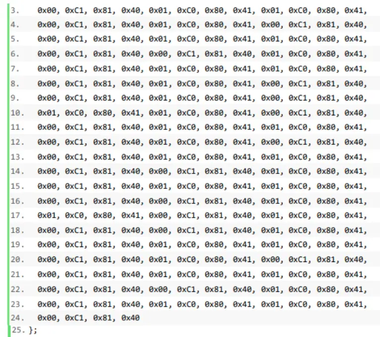
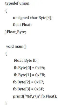
Appendix 2: Analysis codes for motor sign parameters
Historical version update notes
| Revision | Release Data | Summary |
| V1.0_0212 | 2020/02/12 | First draft |
| V1.1_0319 | 2021/03/19 | Readjustment |
| V1.2_0628 | 2021/6/28 | Add Human sensitivity explained and fall sensitivity explained |
| V1.3_0906 | 2021/9/06 | Human sensitivity revised from 0-9 to 1-10 |
| V1.5_0210 | 2022/2/10 | Add initialization success command protocol |
| V1.6_0221 | 2-22/2/21 | Adding a forced entry unmanned gear protocol |
| V1.7_0224 | 2022/2/24 | Addition of a “none” protocol in the entry and exit states and a protocol for reporting heart rate data |


