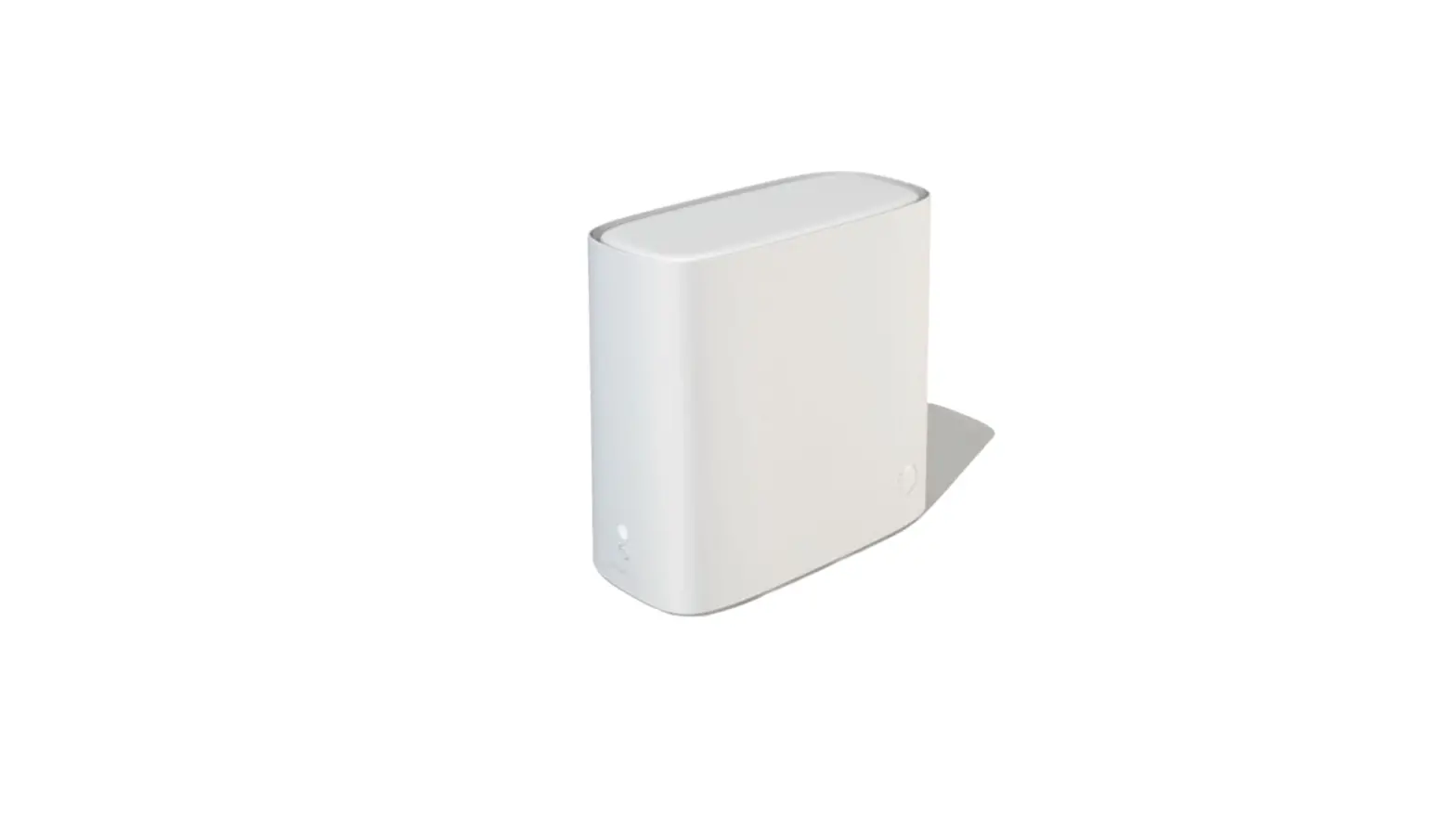
HUMAX BGW320-500 Broadband Gateway

HUMAX Copyrights and Trademarks
© 2019 HUMAX Co., Ltd. All Rights Reserved Reserved.
- No part of this publication may be reproduced in any form or by any means or used to make any derivative work (such as translation, transformation, or adaptation) without written permission from HUMAX Co., Ltd. (“HUMAX”).
- HUMAX reserves the right to revise this publication and to make changes in content from time to time without obligation on the part of HUMAX to provide notification of such revision or change.
- HUMAX and the HUMAX logo are all trademarks of HUMAX Co., Ltd.
- Other trademarks and trade names may be used in this document to refer to either the entities claiming the marks or the names of their products.
- HUMAX disclaims proprietary interest in the marks and names of others.
- HUMAX provides this guide without warranty of any kind, implied or expressed, including, but not limited to, the implied warranties of merchantability and fitness for a particular purpose. HUMAX may make improvements or changes in the product(s) described in this manual at any time.
- The capabilities, system requirements and/or compatibility with third third-party products described herein are subject to change without notice.
HUMAX BGW320 BGW320-500 XGS XGS-PON Broadband Gateway Introduction
The BGW320BGW320-500 XGS XGS-PON Broadband Gateway hardware platform can host different software. The Advanced Residential Gateway supports VoIP, IPv6, video delivery, security firewall, and extensive remote management features.
The BGW320-500 Broadband Gateway delivers robust video, primary line telephony, and high high-speed data over broadband networks via high high-speed Internet connectivity. The four Gigabit Ethernet ports can be separated into different services allowing the configuration of dedicated ports for data. It is designed for advanced XGSXGS-PON network service deployments and supports Quality of Service ( QoS) enabled features including:
- Simultaneous use of phone, video, and high high-speed data over any one of the available WAN interfaces
- IPTV video
- Concurrent Wi -Fi support for 4×4 802.11ax on 2.4GHz, and 4×4 802.11ax on 5GHz both High and Low band.
- Primary line VoIP telephone service
About HUMAX Documentation
This guide presents basic operational concepts and provides step step-by -step instructions for the hardware installation and basic troubleshooting of the HUMAX BGW320 BGW320-500 XGS XGS-PON Broadband Gateway.
Note For the purposes of this manual the HUMAX BGW320 BGW320-500 XGS XGS-PON Broadband Gateway may also be referred to simply as the gateway.
Documentation Hyperlinks
The hyperlink resides in the page number that follows the title. For example, to access Hardware Gateway Installation in the hyperlink below, hover the mouse over the page number in parenthesis until the finger pointer appears, and then click.
Document Organization
This hardware install and operation guide consists of six product information chapters presented as follows:
- HUMAX BGW320-500 XGS-PON Broadband Gateway Introduction — Describes the HUMAX® document suite , purpose, and structure of this
- Preliminary Safety Instructions — Provides power supply, telecommunication, and ventilation safety instructions.
- Hardware Gateway Installation — Provides the rear panel illustration, a cabling overview, and procedures to perform BGW320BGW320-500 XGS XGS-PON Broadband Gateway connections for the power adapter, Optic Module, wired Ethernet, wireless devices, Internet, and VoIP telephones.
- Basic Troubleshooting — Provides simple suggestions for troubleshooting problems with the initial configuration of the gateway.
- Technical Specifications — Presents system and device specifications and important compliance and safety statements.
- Important Safety Instructions — Provides product, telecommunication, and electrical cautionary information, as well as conformance, radiation, and gateway disposable information.
Preliminary Safety Instructions
Warning:
Do not use before reading these instructions.
Do not connect the Ethernet ports to a carrier or carriage service provider’s telecommunications network or facility unless:
- You have the written consent of the network or facility manager, or
- The connection is in accordance with a connection permit or connection rules.
Connection of the Ethernet ports may cause a hazard or damage to the telecommunication network or facility, or persons, with consequential liability for substantial compensation.
Power Supply Installation
Connect the power supply cord to the power jack on the BGW320-500 XGS-PON Broadband Gateway. Plug the power supply into an appropriate electrical outlet.
Warning: The power supply must be connected to a mains outlet with a protective earth connection. Do not defeat the protective earth connection.
Warning: Use only the power supply and cord that came with the BGW320-500 XGS-PON Broadband Gateway. Failure to use the authorized power supply and cord may cause electric shock, fire, bodily injury, and/or property damage. If the power supply or cord becomes damaged or needs to be replaced, to obtain an authorized replacement please contact AT&T customer service by phone
(1.800.288.2020) or via website (www.att.com/support).
Caution: Depending on the power supply provided with the product, either the direct plug-in power supply blades, power supply cord plug or the appliance coupler serves as the mains power disconnect. It is important that the direct plug-in power supply, socket-outlet or appliance coupler be located so it is readily accessible.
Telecommunication Installation
When using telephone equipment, basic safety precautions should always be followed to reduce the risk of fire, electric shock, and injury, including the following:
- This device is intended for indoor use only.
- Warning: Do not install this gateway outdoors.
- Do not use this product near water, for example, near a bathtub, washbowl, and kitchen sink or laundry tub, in a wet basement or near a swimming pool.
- Avoid using a telephone (other than a cordless type) during an electrical storm. There may be a remote risk of electrical shock from lightning.
- Do not use the telephone to report a gas leak in the vicinity of the leak.
Caution: The external phone should be UL listed, and the connections should be made in accordance with Article 800 of the National Electric Code (NEC).
Caution: To reduce the risk of fire, use only No. 26 AWG or larger telecommunication line cord.
Optic Module Installation
When using SFP/SFP+ optic module, basic safety precautions should always be followed to reduce the risk of fire, electric shock, and injury, including the following:
- It is strongly recommended that you do not install or remove the SFP module with fiber-optic cables attached to it because of the potential of damaging the cable, the cable connector, or the optical interfaces in the SFP/SFP+ optic module. Disconnect all cables before removing or installing an SFP/SFP+ optic module.
- Warning: Removing and inserting an SFP module can shorten its useful life, so you should not remove and insert SFP modules any more often than is absolutely necessary.
Caution: To reduce the risk of fire, use only provided SFP/SFP+ optic module..
Product Ventilation
The BGW320-500 XGS-PON Broadband Gateway is intended for use in a consumer’s home. Position the device in an upright vertical position located where ambient temperatures remain within a range of 32°- 107°F (0°- 41.7°C). The BGW320-500 XGS-PON Broadband Gateway should not be used in locations exposed to outside heat radiation or where it is subject to trapping of its own heat. The product should have at least two inches of clearance on all sides except the bottom when properly installed and should not be placed inside tightly enclosed spaces unless proper ventilation is provided.
WARNING: RISK OF OVERHEATING IF NOT PROPERLY VENTILATED
- Do not place any heat sources directly above the top cover or below the bottom cover.
- Only Place the product on the flat surface, such as a desk or shelf.
SAVE THESE INSTRUCTIONS
Hardware Gateway Installation
A BGW320-500 XGS-PON Broadband Gateway cabling overview, as well as rear panel illustration, is provided below. Also provided are procedures to perform BGW320-500 XGS-PON Broadband Gateway connections for the power adapter, optic module, wired Ethernet, wireless devices, Internet, and analog telephone.
The following diagram illustrates BGW320-500 XGS-PON Broadband Gateway connections to the Internet using DSL Broadband. Phone and power adapter connections are also illustrated.
BGW320-500 XGS-PON Broadband Gateway Cabling Overview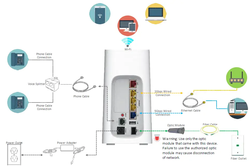
Warning: Use only the optic module that came with this device. Failure to use the authorized optic module may cause disconnection of network.
Warning: Use only the power supply and cord that came with this device. Failure to use the authorized power supply and cord may cause electric shock, fire, bodily injury, and/or property damage.
Alternatively, you can connect the BGW320-500 XGS-PON Broadband Gateway to the Internet using the WAN Ethernet port labeled ONT. See Connecting the BGW320-500 XGS-PON Broadband Gateway to the Internet (page 14) for the detailed procedures regarding this setup.
BGW320-500 XGS-PON Broadband Gateway Rear Panel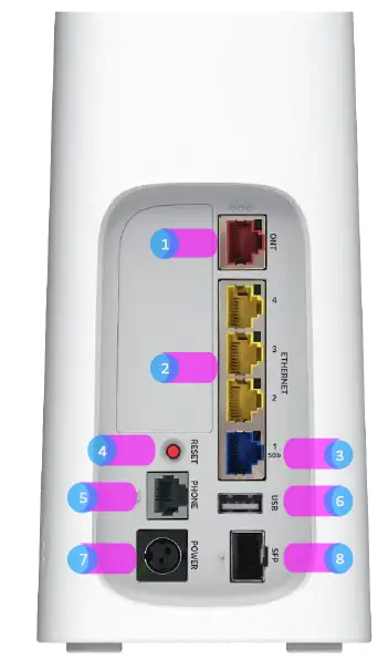
| Number | Port | Description |
| 1 | ONT Port | The Optical Network Terminal fiber optic connector. |
| 2 | Ethernet #1, #2, #3 | Provide connection for up to three(3) 1Gbps Ethernet devices, such as PCs and other devices. |
| 3 | Ethernet #4 | 5Gbps Ethernet port for PCs and Other devices. |
| 4 | Reset Button | Used to reboot the gateway (if held for less than 10 seconds) or perform a factory default restore (if held for longer than 10 seconds). |
| 5 | Phone Lines #1 and #2 | Provides connection for analog phone. A voice line splitter is required when connecting two phones. |
| 6 | USB #1 | Universal Serial Bus connections 2.0 for USB devices. |
| 7 | Power Port | Used to power the gateway on/off. |
| 8 | SFP/SFP+ Cage | Provide connection for Optic module insert and remove. |
Connecting the Power Adapter
The power adapter supplies power to the BGW320-500 XGS-PON Broadband Gateway.
- Connect the appropriate end of the power adapter cable to the BGW320-500 XGS-PON Broadband Gateway rear panel POWER port.
- Connect the power plug end to the electrical outlet.
After the BGW320-500 XGS-PON Broadband Gateway is powered on, the power light blinks white. For all power light indications, see Status Indicator Lights (page 18, 19, 20) under Basic Troubleshooting.
Warning: Use only the power supply and cord that came with the BGW320-500 XGS-PON Broadband Gateway. Failure to use the authorized power supply and cord may cause electric shock, fire, bodily injury, and/or property damage. If the power supply or cord becomes damaged or needs to be replaced, to obtain an authorized replacement please contact AT&T customer service by phone
(1.800.288.2020) or via website (www.att.com/support).
Connecting Computers to the BGW320-500 XGS-PON Broadband Gateway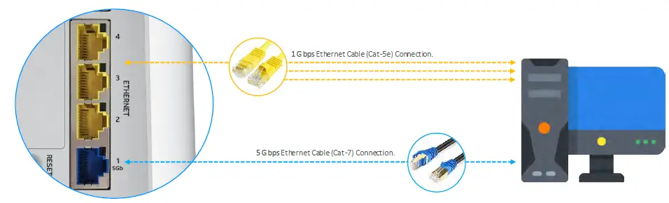
The first computer you connect can be used to configure the BGW320-500 XGS-PON Broadband Gateway settings. You can connect more computers and other devices to the BGW320-500 XGS-PON Broadband Gateway using wireless or wired Ethernet.3- 2-1. Connecting Devices Using Wired Ethernet
The BGW320-500 XGS-PON Broadband Gateway has four wired Ethernet ports (three 1Gbps Ethernet ports and one 5Gbps Ethernet port) that can be used to connect computers or other devices.
As shown in the illustration below, to connect a computer to the BGW320-500 XGS-PON Broadband Gateway:
- Connect one end of the Ethernet cable to one of the Ethernet ports on the BGW320-500 XGS-PON Broadband Gateway.
- Connect the other end of the cable to the Ethernet port on the computer.
Note: To use 5Gbps Ethernet port, recommended to connect with CAT-7 Ethernet cable.
Connecting a Computer to a Ethernet Port of the BGW320-500 XGS-PON Broadband Gateway
After the gateway recognizes the computer, the Ethernet LED or 5G Ethernet LED turns steady green when the computer starts transferring data with the gateway. See Status Indicator Lights (page 18) under Basic Troubleshooting for all Ethernet light indications.
Connecting Devices Using Wi-Fi
The BGW320-500 XGS-PON Broadband Gateway has an integrated Wi-Fi access point to which users can use to connect Wi-Fi devices. By default, the BGW320-500 XGS-PON Broadband Gateway is configured with a Wi-Fi network name (SSID) and is WPA-PSK/WPA2-PSK security enabled.
To connect a Wi-Fi device:
On the Wi-Fi device, view the available Wi-Fi networks. The specifics of how you do this depend on the device to which you are connecting. The default Wi-Fi network name (SSID) and the Wi-Fi password (e.g., encryption key) are printed on both Removable label and Back Panel label of the BGW320-500 XGS-PON Broadband Gateway. Select the appropriate Wi-Fi network name and connect.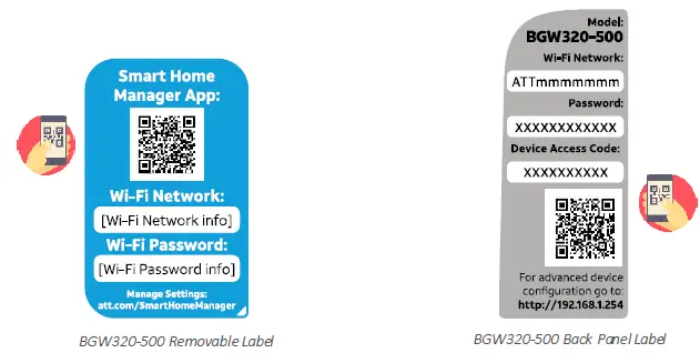
NOTE: Download the “Smart Home Manager” App. by scanning QR code in the Removable Label.
NOTE: Scan the QR code in the back panel label after downloading the “Smart Home Manager App”.
- At the prompt, enter the Wi-Fi password.
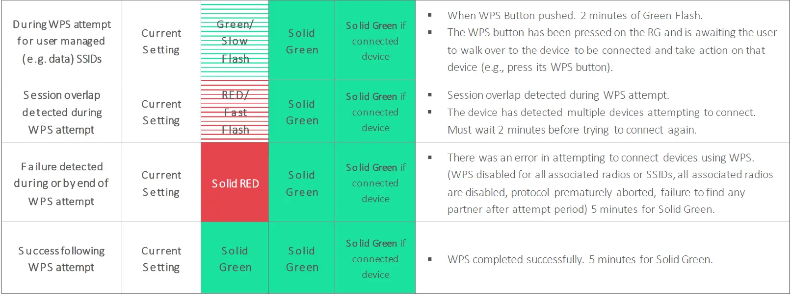
To simplify Wi-Fi device connection to the BGW320-500 XGS-PON Broadband Gateway: You can configure Wi-Fi Protected Setup (WPS) to the network using the PUSH method. - The PUSH method establishes Wi-Fi connectivity if you push the WPS button on the front panel of the BGW320-500 XGS-PON Broadband Gateway and on the Wi-Fi device.
- Upon WPS button push, the WPS button light green slow flash and turn to steady green once WPS is completed successfully.
- See Status Indicator Lights (page 18,19,20) under Basic Troubleshooting for all WPS indications.
Connecting the BGW320-500 XGS-PON Broadband Gateway to the Internet
Note: The appropriate port to connect to the Internet is based on the service configuration from AT&T. Do not change the port used unless instructed to do so.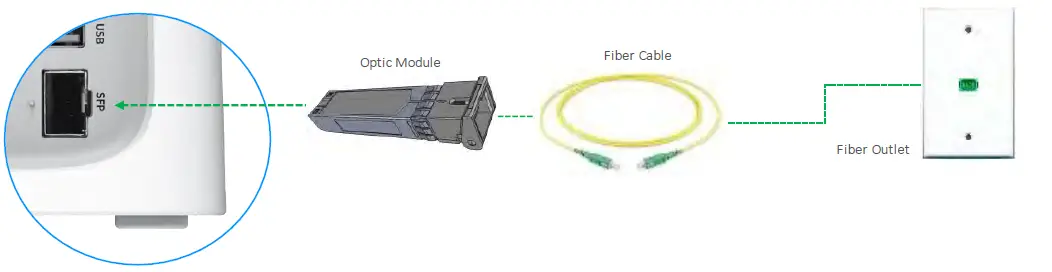
Warning: DO NOT REMOVE THE OPTIC MODULE AFTER INITIAL INSTALLATION WITHOUT ANY INSTRUCTION FROM AT&T.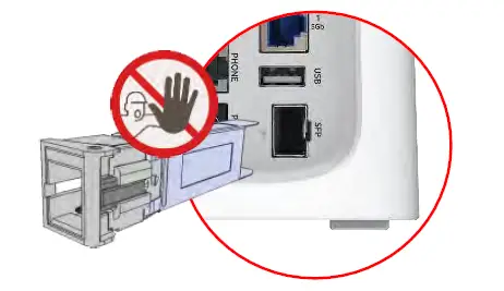
Only one of these wiring arrangements can be used at the same time and attempting to use both may interfere with your service.
The optic module port which completed for installation can be used to connect the BGW320-500 XGS-PON Broadband Gateway to the Internet:
- Connect one end of the fiber cable to the optic module port on the BGW320-500 XGS-PON Broadband Gateway.
- Connect the other end of the fiber cable to the wall outlet.
After the BGW320-500 XGS-PON Broadband Gateway recognizes the connection, the service LED will light steady white. See Status Indicator Lights (page 18, 19, 20) under Basic Troubleshooting for all Broadband light indications.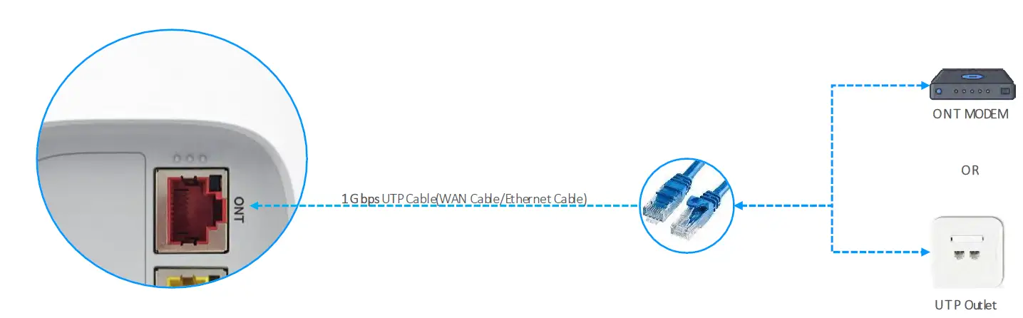
Alternatively, you can connect the BGW320-500 XGS-PON Broadband Gateway to the Internet using the WAN Ethernet port (labeled ONT):
- Connect one end of an Ethernet cable to the WAN Ethernet port on the BGW320-500 XGS-PON Broadband Gateway.
- Connect the other end of the cable to the operator provided WAN Ethernet jack or ONT.
- After the BGW320-500 XGS-PON Broadband Gateway recognizes the connection, the WAN Port LED will flash steady green and service LED will lights steady white. See Status Indicator Lights (page 18, 19, 20) under Basic Troubleshooting for all Broadband light indications.
Connecting Telephone for VoIP Service
The BGW320-500 XGS-PON Broadband Gateway includes one RJ-14 port (labeled Phone) with the capacity to support one phone lines using a splitter or multi-jack adapter.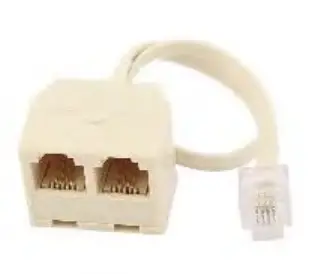
Note: The BGW320-500 XGS-PON Broadband Gateway supports two VoIP lines over one RJ14 (FXS) VoIP port. To connect two phone lines, an inner and outer pair splitter adapter must be attached to the RJ14 (FXS) VoIP port to terminate both lines.
Warning: Do not connect the VoIP lines to your current home telephone wiring, especially if your home has an alarm system. Ensure that you are subscribed to VoIP service for this interface to be used.
As shown in the figures below, to connect phones directly to your gateway:
- Connect one end of the phone cable to the gray Phone Lines connector on the BGW320-500 XGS-PON Broadband Gateway.
- To connect to the telephone(s), do one of the following:
- For one phone, connect the phone cable directly to the telephone.
- For two phones, connect the phone cable to a splitter and then to the phones.
For one phone connection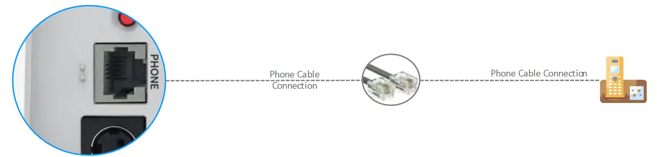
For two phones connection 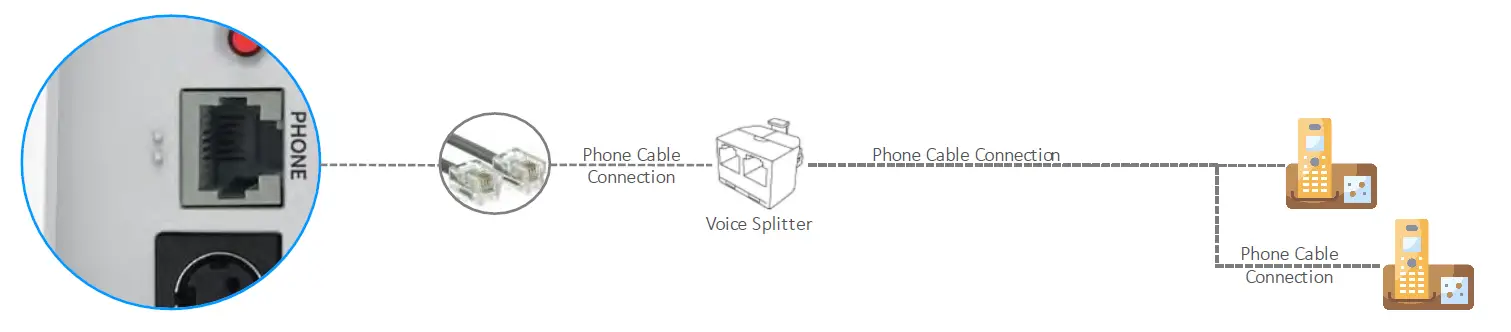
Note: To prevent interference with cordless phones, ensure that the BGW320-500 XGS-PON Broadband Gateway is at least 5 feet (1.5 m) from any cordless phone base station.
After the gateway recognizes the phones, the service LED lights steady white when the associated phone is in use. See Status Indicator Lights (page 18, 19, 20) under Basic Troubleshooting for all Phone light indications.
Basic Trouble Shooting
This chapter provides simple troubleshooting suggestions for issues with the initial configuration of the BGW320-500 XGS-PON Broadband Gateway. The following topics are covered:
- Status Indicator Lights
- Rear Panel Connectors
- Factory Reset Switch
Before troubleshooting:
- Read this guide, including Hardware Gateway Installation and all of the subtopics.
- Set the TCP/IP controls on the PC to obtain an IP address automatically.
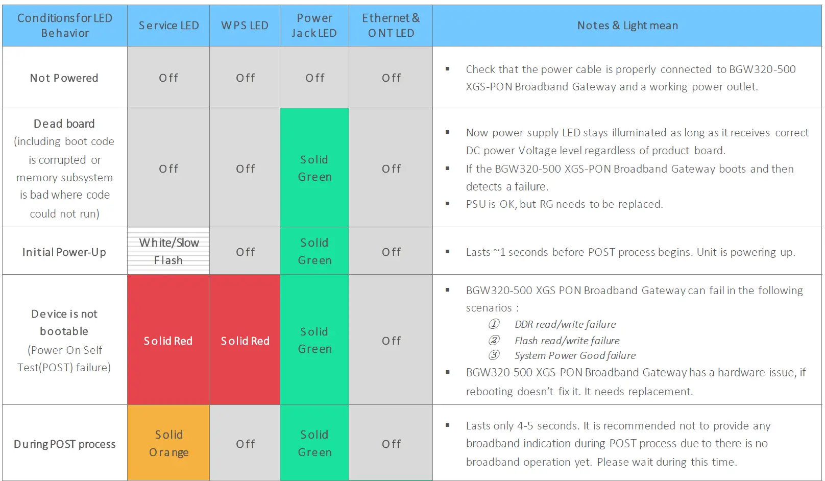
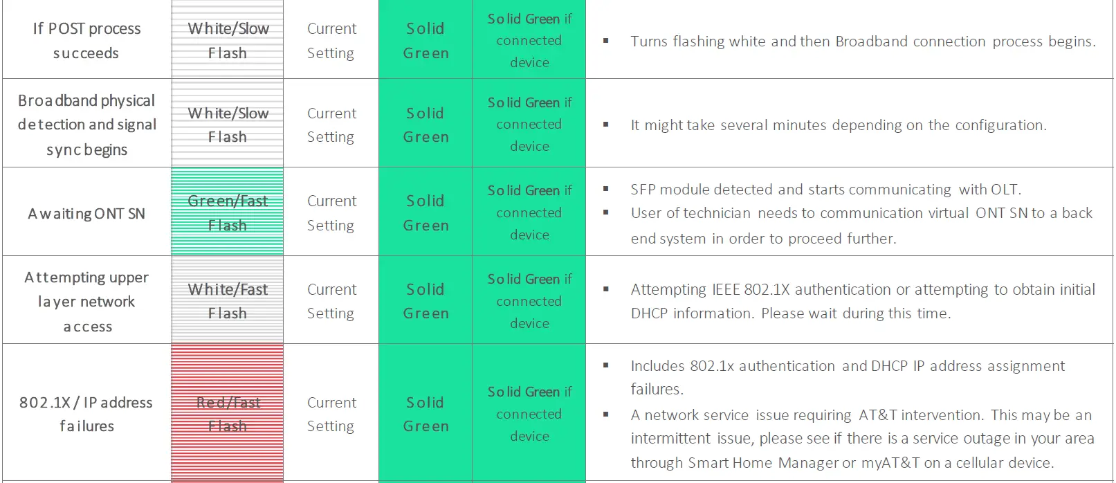
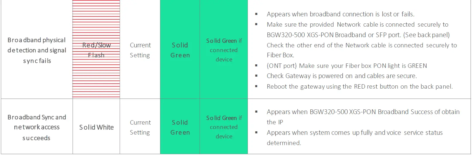
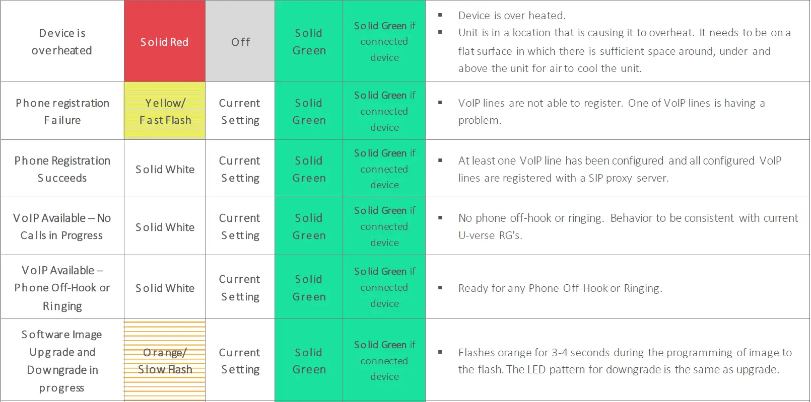
Status Indicator Lights
Check the status indicator lights (LEDs) to begin troubleshooting. Use the front and rear view graphics that follow, as well as the LED Activity descriptions table to interpret the LED indicators.
BGW320-500 XGS-PON Broadband Gateway Status Indicator Lights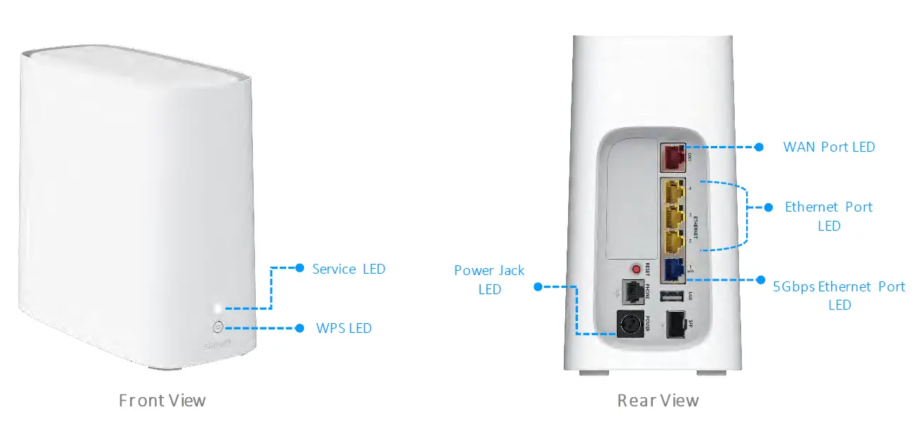
Problem Isolation
If a status indicator light does not look correct, look for these possible problems:
| LED Not Lit : | Possible Problems |
|
S ervice LED (Front Panel) does not lights after connecting the Power Supply Unit. |
§ Check the rear panel Power Jack LED, which is to the left of the connector for the cord from the power adapter. § If the rear panel Power Jack LED is on, contact AT&T by phone (1.800.288.2020) or via website § If the rear panel Power LED is off: ° Make sure the power adapter is plugged into the gateway properly. For location, see Rear Panel Connectors (page 21). ° Try a known good wall outlet. ° If a power strip is used, make sure it is switched on. |
|
S ervice LED (Front Panel) does not lights after installation of SFP module and connected with Fiber Cable. |
§ Make sure that SFP optic module installed properly. § Make sure that you are using the correct Fiber cable. § Make sure the Fiber cable is plugged into the correct wall jack. § Make sure the Fiber cable is plugged into the optic module port on the BGW320-500 XGS-PON broadband gateway. § Make sure the Fiber line has been activated by AT&T. |
|
Ethernet Ports (Back Panel) does not lights after connecting with the Ethernet cables |
§ Make sure that you are using the yellow Ethernet cable. § Make sure the Ethernet cable is securely plugged into the Ethernet jack on the PC. § Make sure the Ethernet cable is securely plugged into the Ethernet port on the BGW320-500 XGS-PON broadband gateway. § Make sure you have Ethernet drivers installed on the PC. § Make sure the PC’s TCP/IP properties for the Ethernet network control panel are set to obtain an IP address via DHCP. § Make sure the PC has obtained an address in the 192.168.1.x range. (You may have changed the subnet addressing.) § Make sure the PC is configured to access the Internet over a LAN. § Disable any installed network devices (Ethernet, HomePNA, Wi-Fi) that are not being used to connect to the BGW320- 500 XGS-PON broadband gateway. |
Rear Panel Connectors
Connectors on the rear panel are depicted below.
BGW320-500 XGS-PON Broadband Gateway Rear Panel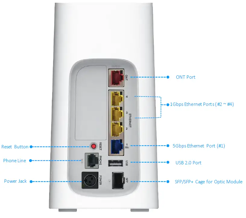
Note: The BGW320-500 XGS-PON Broadband Gateway supports two voice lines over one RJ14 (FXS) analog port. To connect two phone lines, an inner and outer pair splitter adapter must be attached to the RJ14 (FXS) analog port to terminate both lines.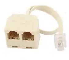
Note: The BGW320-500 XGS-PON Broadband Gateway supports one SFP/SFP+ Cage. To install Optic Module into SFP/SFP+ Cage, follow the guidance from AT&T.
Warning: DO NOT REMOVE THE OPTIC MODULE AFTER INITIAL INSTALLATION WITHOUT ANY INSTRUCTION FROM AT&T.
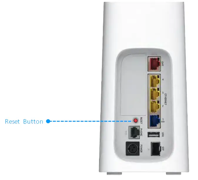
Factory Reset Switch
The Reset switch will result in a reboot of the BGW320-500 XGS-PON Broadband Gateway. Depending on the software loaded on the BGW320-500 XGS-PON Broadband Gateway, holding it for an elongated duration of time may reset the device to factory defaults.
- Referring to the diagram below, find the round Reset switch opening.
BGW320-500 XGS-PON Broadband Gateway Rear Panel
- Press the reset button to initiate the following:
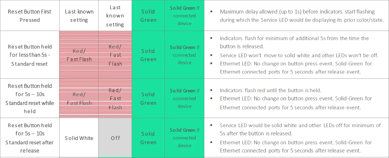
- Press the reset button for less than 10 seconds to standard reboot the BGW320-500 XGS-PON Broadband Gateway, the Service LED on the front panel will respond immediately and lights red flash within 10 second of the reset button being pressed.
- The service LED will lights fast flash red during the button is still being pressed and turns steady white once the reset button released within 10 seconds.
- If the reset button is held for more than 10 seconds, it will start to factory reset.
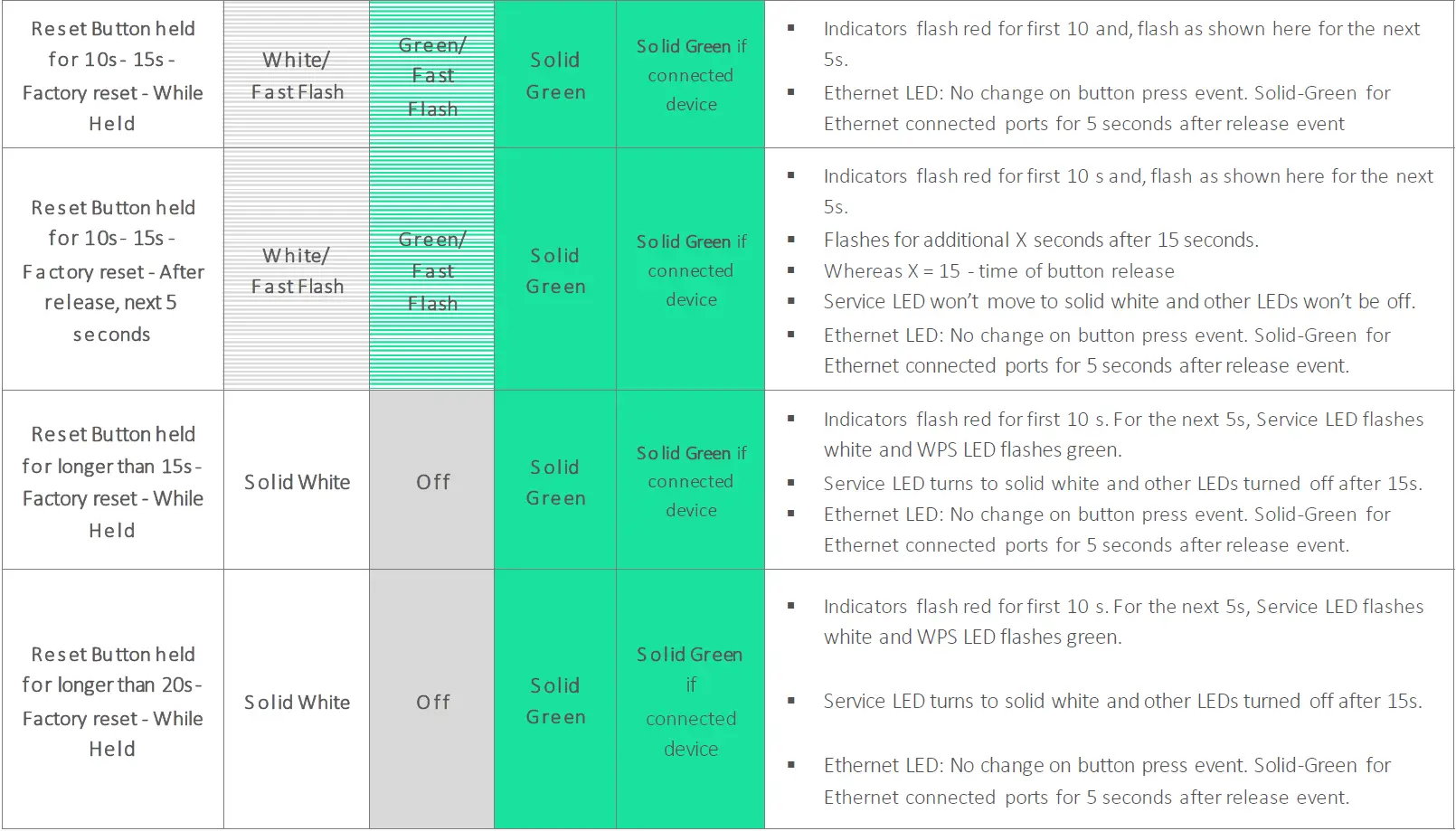
- Press the reset button and hold for longer than 10 seconds, to reset the device to the factory default shipped settings. If the button is held for ten seconds, the service LED will start to blink white flash and WPS LED will start to blink green flash.
- If the reset button is held more than 15 seconds, service LED will turn on steady white and WPS LED will be turned off, and start to factory reset.
Warning: Resetting the BGW320-500 XGS-PON Broadband Gateway to factory defaults will require all configured settings to be reconfigured.
Technical Specifications and Safety Information
Dimensions and Interfaces
| Dimensions and Interfaces | |
| Dimensions/Weight/ Placement | § Dimensions : 200mm[L]X 100mm[W] X 188mm[H] Without foot / 191mm[H] With Foot § Weight : 1.688kg § Placement : Vertical placement only on a flat surface, such as desk or shelf |
|
Communications interfaces | § Tri-Band Wi-Fi support for 802.11b/g/n/ac and 802.11ax § Three-ports for 10/100/1000Base-T Ethernet switch, RJ-45 § One-port for 2.5G/5GBase-T Ethernet switch, RJ-45 § Single-port voice FXS, RJ-14 § One-port USB 2.0 |
|
WAN interfaces |
§ One port SFP/SFP+ Cage for GPON/XGS-PON optic module § One-port 10/100/1000 Ethernet, RJ-45 |
|
Tri-Band Wi-Fi |
§ 802.11 b/g/n/ac and 802.11ax. |
|
Wi-Fi Characteristics |
§ 802.11ax 2.4GHzsupport, 4×4 § 802.11ax 5GHz support, 4×4 for both Low-Band and High-Band |
Power Supply
- This product is intended to be supplied with a Listed Direct Plug-In AC/DC power adapter rated @12V 4A DC for all BGW320-xxx models.
- The AC/DC power adapter supplied with this product is designed to ensure your personal safety and to be compatible with this equipment. Use only the power adapter that was provided with the gateway.
Environment
- Operating temperature: 0°C to 41.7°C (32° F to 107°F); 8% to 95% (Non Condensing) Relative Humidity
- Storage temperature: –40°C to 80° C (–40° F to 176°F)
Agency Approval
North America
- Safety Approvals:
- United States – UL 62368-1
- EMC:
- United States – FCC Part 15 Class B, Subparts B, C, and E
Caring for the Environment by Recycling
Recycling your HUMAX Equipment
Please do not dispose of this product with your residential or commercial waste. Some countries or regions have set up systems to collect and recycle electrical and electronic waste items. Contact your local authorities for information about practices established for your region. If collection systems are not available, contact HUMAX Customer Service for assistance at https://humaxdigital.com/environmental-management.
Important Safety Instructions
Warning: Do not use before reading these instructions.
Do not connect the Broadband Ethernet port (labeled ONT) to a carrier or carriage service provider’s telecommunications network or facility unless:
- A) You have the written consent of the network or facility manager, or
- B) The connection is in accordance with a connection permit or connection rules.
Connection of the Ethernet ports may cause a hazard or damage to the telecommunication network or facility, or persons, with consequential liability for substantial compensation.
WARNINGS
The power supply must be connected to an outlet. Do not defeat the protective earth connection. The direct plug-in power supply serves as the main power disconnect; locate the direct plug-in power supply near the product for easy access.
Product Ventilation
The gateway is intended for residential use. Position the gateway in an upright vertical position and locate it where temperatures remain within a range of 32°– 107°F (0° – 41.7°C) and where heat from the unit itself is not trapped. There must be at least two inches (2″) of clearance on all sides except the bottom.
Telecommunication Installation Cautions
- Never install telephone wiring during a lightning storm.
- Never install telephone jacks in wet locations unless the jack is specifically designed for wet locations.
- Never touch uninsulated telephone wires or terminals unless the telephone line has been disconnected at the network interface.
- Use caution when installing or modifying telephone lines.
- Avoid using a telephone (other than a cordless type) during an electrical storm. There may be a remote risk of electric shock from lightning.
- Do not use the telephone to report a gas leak in the vicinity of the leak.
Optic Module Installation Cautions
It is strongly recommended that you do not install or remove the SFP module with/without fiber-optic cables attached to it because of the potential of damaging the cable, the cable connector, or the optical interfaces in the SFP module. Disconnect all cables before removing or installing an SFP module. Removing and inserting an SFP module can shorten its useful life, so you should not remove and insert SFP modules any more often than is absolutely necessary.
Electrical Safety Advisory
Telephone companies report that electrical surges, typically lightning transients, are very destructive to customer terminal equipment connected to AC power sources. This has been identified as a major nationwide problem. Therefore it is advised that this equipment be connected to AC power through the use of a surge arrestor or similar protection device.
Declaration of Conformance
Warning: This is a Class B product. In a domestic environment this product may cause radio interference, in which case the user may be required to take adequate measures. Adequate measures include increasing the physical distance between this product and other electrical devices. Changes or modifications to this unit not expressly approved by the party responsible for compliance could void the user’s authority to operate the equipment.
United States:
This device complies with Part 15 of the FCC Rules.
Operation is subject to the following two conditions:
- This device may not cause harmful interference, and
- This device must accept any interference received, including interference that may cause undesired operation.
This equipment has been tested and found to comply with the limits for a Class B digital device, pursuant to Part 15 of the FCC Rules. These limits are designed to provide reasonable protection against harmful interference in a residential installation. This equipment generates, uses, and can radiate radio frequency energy and, if not installed and used in accordance with the instructions, may cause harmful interference to radio communications. However, there is no guarantee that interference will not occur in a particular installation. If this equipment does cause harmful interference to radio or television reception, which can be determined by turning the equipment off and on, the user is encouraged to try to correct the interference by one or more of the following measures:
- Reorient or relocate the receiving antenna.
- Increase the separation between the equipment and receiver.
- Connect the equipment into an outlet on a circuit different from that to which the receiver is connected.
- Consult the dealer or an experienced radio/TV technician for help.
IEC Symbol Descriptions
| Symbol | Title/Meaning/Referent | Reference Number | Function/Description |

|
• Class II equipment |
• IEC 60417-5172 | • To identify equipment meeting the safety requirements specified for Class II equipment according to IEC 61140. • Double insulated Class II equipment (IEC 60417-5172). • Do not require an earth connection. |
 | • For indoor use only | • IEC 60417-5957 | • To identify electrical equipment designed primarily for indoor use. |
| • Direct current | • IEC 60417-5031 | • To indicate on the rating plate that the equipment is suitable for direct current only; to identify relevant terminals. |
Caution: IEC symbols are marked at bottom label of the BGW320-500 XGS-PON Broadband Gateway. Product usage must be followed with IEC guidance.
FCC Compliance Statement
NOTE: This equipment has been tested and found to comply with the limits for a Class B digital device, pursuant to part 15 of the FCC Rules. These limits are designed to provide reasonable protection against harmful interference in a residential installation. This equipment generates, uses and can radiate radio frequency energy and, if not installed and used in accordance with the instructions, may cause harmful interference to radio communications. However, there is no guarantee that interference will not occur in a particular installation. If this equipment does cause harmful interference to radio or television reception, which can be determined by turning the equipment off and on, the user is encouraged to try to correct the interference by one or more of the following measures:
- Reorient or relocate the receiving antenna.
- Increase the separation between the equipment and receiver.
- Connect the equipment into an outlet on a circuit different from that to which the receiver is connected.
- Consult the dealer or an experienced radio/TV technician for help.
FCC Caution
Caution: Any changes or modifications not expressly approved by the party responsible for compliance could void the user’s authority to operate this equipment. This transmitter must not be co-located or operating in conjunction with any other antenna or transmitter.
Radiation Exposure Statement
This equipment complies with FCC radiation exposure limits as set forth for an uncontrolled environment. This equipment should be installed and operated maintaining a minimum distance of 31 cm (12 inches) between the device and your body.
HUMAX Contacts
Technical Services
For technical support on HUMAX products you can contact us on the web.
On the Web
www.humaxdigital.com
There you will be able to access:
- Support Contact Information for all products
- Knowledge Base Information (also known as Solutions)
- User Documentation
- Current open support cases.
HUMAX AMERICAS REGIONAL HEADQUARTER
15641 Red Hill Avenue Suite 150 Tustin CA 92780
COLORADO RIGIONAL OFFICE(SALES & BUSINESS DEVELOPMENT)
6400 S.Fiddlers Green Circle Suite 250 Greenwood Village CO 80111
© Copyright 2019 HUMAX. All rights reserved.
The information and specifications included are subject to change without notice.


