Orbbec Zora E1 Development Board Instruction Manual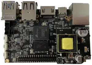
Product hardware specification
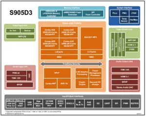
| CPU | Amlogic S905D3 Quad-core Cortex-A55 1.9GHz |
| GPU | Mali-G31MP2 GPU 800MHz,Support OpenGL ES3.2, Vulkan 1.0, OpenCL 2.0 |
| NPU | 1.2 TOPS,Support 8bit/16bit,Support TensorFlow、Caffe |
| DDR memory | LPDDR4/4X 2G ,Support eMMC 5.1,16G,32G,64G |
| Multi Media | Supports 4K VP9 and 4K 10bits H265/H264 video decoding, up to 60fps 1080p Multiformat Video Decoding (VC-1, MPEG-1/2/4, VP8) 1080p video coding, supports H.264 focus VP8 format Video post-processor: de-interleaving, denoising, edge / detail / color optimization |
| Camera interface | 1 x 2 lane MIPI-CSI |
| USB | 2 x USB 3.0 Type A (two stack share one bandwidth) 2 x USB 2.0 Type A (host) |
| serial port | 2 x UART through GPIO |
| Display interface | 1 x HDMI 2.1 (audio output is supported) 1 x 2 lane MIPI-DSI (up to 1920×1080) |
| Wireless interface | WiFi/Bluetooth two-in-one module: WiFi 2.4GHz/5GHz,Bluetooth 5.0 |
| Wired network interface | RJ45 (10/100/1000M) x 1, need to support PoE through expansion card, wake on lan (WOL) |
| Microphone interface | On board microphone |
| Debugging | Type-C debugging |
| IR | Support infrared, Bluetooth remote control |
| Button | Power button, reset button, upgrade button |
| Micro SD | 1 x Micro SD |
| Antenna interface | PCB printed antenna |
| LED interface | Support |
| I2C | 2*I2C through GPIO |
| GPIO | 40 pin GPIO |
| I2S | 1*I2S through GPIO |
| RTC | 0.8mm pitch header |
| PWM interface | 2 x PWM |
| Digital-to-analog conversion | ADC through GPIO |
| Power input | U USB TYPE C can supply at least 5V-3A power |
| Power Output | 1-12V, 2-5V, 1-3.3V power output through GPIO |
| Firmware upgrade | Support local SD card upgrade or USB upgrade |
| OS | Android 9.0; Linux Ubuntu 18.04 |
| Size | 82 mm x 56 mm |
| Operating temperature | 0-50℃ |
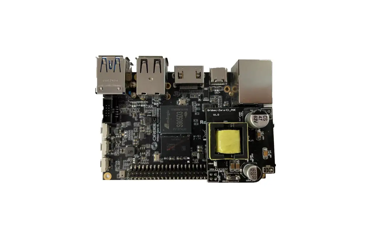
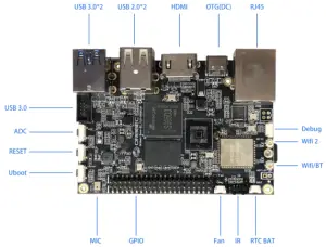
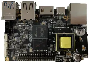
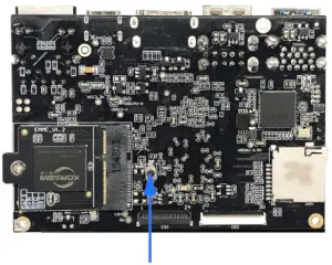
Product picture
- Diagram of the interface on the front of the board(82*56mm)

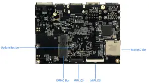
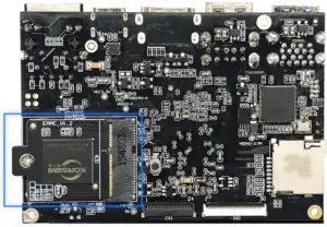
- Interface diagram on the back of the board

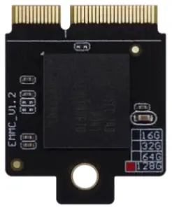
Introduction to the use of EMMC module
- Emmc Synopsis
EMMC adopts plug-and-pull module with a capacity of 8G (customizable 16G, 32G, 64G) - Module Picture (28*22mm)
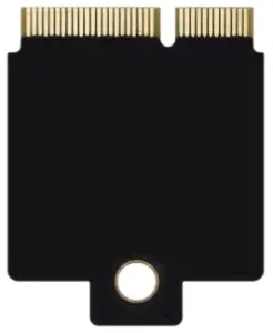
Front
Back - EMMC installation diagram (fixed by screws and board studs)

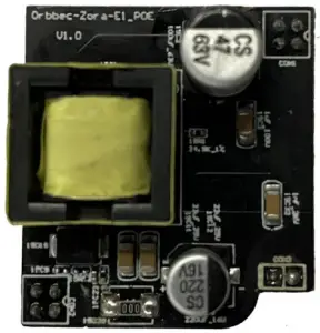
Introduction to the use of POE module
- Module Picture

- POE module support IEEE802.3af, IEEE802.3af is a new international extension protocol standard of Power over Ethernet ((Power over Ethernet, PoE) technology. The IEEE 802.3af-2003 standard provides a guarantee of 15.4W DC power for a machine (the minimum can be 44V DC and 350mA)
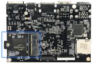
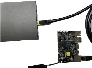
- Complete the installation of the poe module on the zora e1 development board

- How to use the zora E1 development board with poe module installed
- Use a switch or router that supports the 802.11af standard to connect the zora E1 development board under Ethernet
- You can transmit data and power through the network cable at the same time.

- The zora E1 development board is working properly.
Zora E1 product usage scenario
The following usage scenarios can be applied to the product:
- Artificial intelligence: face recognition, passenger flow statistics, machine detection and behavior analysis.
- 3D visual media platform: video conference, webcast and distance education.
- The field of Internet of things: smart home, smart logistics and industrial online monitoring.
Download of burning tools and firmware
- The two kinds of system firmware, Android 9.0 and ubuntu 18.04 firmware burn in the same way, need to use usb tool tool for burning.
- Download address of burning tool and firmware
Android Firmware download address www.orbbec.com.cn/sys/37.html# Ubuntu Firmware download address www.orbbec.com.cn/sys/37.html# USb Burn Tool download address www.orbbec.com.cn/sys/37.html#
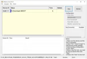
Detailed description of burning firmware
(Android firmware burns in the same way as Ubuntu firmware)
- PC PC requires detailed explanation:
- The system is a windows 7 system or a windows 10 operating system
- Turn off antivirus software
- support usb2.0 high-speed mode or usb3.0
- Use the development board update upgrade button to burn firmware
- Ensure that the eMMC module is installed correctly on the development board

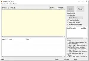
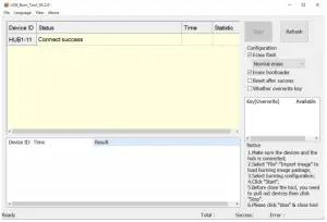
- Open the usb burn tool v2.xxx Burning tool

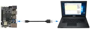
- Long press the update button of the development board

- Press and hold the update button while using the type-c usb cable to connect: the otg (type-c) interface and the PC end of the development board

- Tool connected successfully

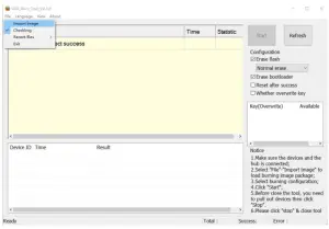
- Import firmware

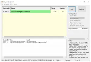
- Click start to enter the burning record
- Burning completed
- Click stop to exit
- Ensure that the eMMC module is installed correctly on the development board
Hardware data
- Chip architecture

FCC Statement
This device complies with part 15 of the FCC rules. Operation is subject to the following two conditions:
- this device may not cause harmful interference, and
- this device must accept any interference received, including interference that may cause undesired operation.
Changes or modifications not expressly approved by the party responsible for compliance could void the user’s authority to operate the equipment.
NOTE: This equipment has been tested and found to comply with the limits for a Class B digital device, pursuant to part 15 of the FCC Rules. These limits are designed to provide reasonable protection against harmful interference in a residential installation. This equipment generates uses and can radiate radio frequency energy and, if not installed and used in accordance with the instructions, may cause harmful interference to radio communications. However, there is no guarantee that interference will not occur in a particular installation. If this equipment does cause harmful interference to radio or television reception, which can be determined by turning the equipment off and on, the user is encouraged to try to correct the interference by one or more of the following measures:
- Reorient or relocate the receiving antenna.
- Increase the separation between the equipment and receiver.
- Connect the equipment into an outlet on a circuit different from that to which the receiver is connected.
- Consult the dealer or an experienced radio/TV technician for help important announcement
Important Note:
Radiation Exposure Statement
This equipment complies with FCC radiation exposure limits set forth for an uncontrolled environment. This equipment should be installed and operated with minimum distance 20cm between the radiator and your body.
This transmitter must not be co-located or operating in conjunction with any other antenna or transmitter.
Country Code selection feature to be disabled for products marketed to the US/Canada.
This device is intended only for OEM integrators under the following conditions:
- The antenna must be installed such that 20 cm is maintained between the antenna and users, and
- The transmitter module may not be co-located with any other transmitter or antenna,
- For all products market in US, OEM has to limit the operation channels in CH1 to CH11 for 2.4G band by supplied firmware programming tool. OEM shall not supply any tool or info to the end-user regarding to Regulatory Domain change. (if modular only test Channel 1-11)
As long as the three conditions above are met, further transmitter testing will not be required. However, the OEM integrator is still responsible for testing their end-product for any additional compliance requirements required with this module installed.
Important Note:
In the event that these conditions cannot be met (for example certain laptop configurations or co-location with another transmitter), then the FCC authorization is no longer considered valid and the FCC ID cannot be used on the final product. In these circumstances, the OEM integrator will be responsible for re-evaluating the end product (including the transmitter) and obtaining a separate FCC authorization.
End Product Labeling
The final end product must be labeled in a visible area with the following” Contains FCC ID: 2A2CL-ZORAE1″
Manual Information to the End User
The OEM integrator has to be aware not to provide information to the end user regarding how to install or remove this RF module in the user’s manual of the end product which integrates this module.
The end user manual shall include all required regulatory information/warning as show in this manual.
Integration instructions for host product manufacturers according to KDB 996369 D03 OEM Manual v01
- List of applicable FCC rules
CFR 47 FCC PART 15 SUBPART C has been investigated. It is applicable to the modular transmitter - Specific operational use conditions
This module is stand-alone modular. If the end product will involve the Multiple simultaneously transmitting condition or different operational conditions for a stand-alone modular transmitter in a host, host manufacturer have to consult with module manufacturer for the installation method in end system. - Limited module procedures
Not applicable - Trace antenna designs
Not applicable - RF exposure considerations
This equipment complies with FCC radiation exposure limits set forth for an uncontrolled environment. This equipment should be installed and operated with minimum distance 20cm between the radiator & your body. - Antennas
This radio transmitter FCCID: 2A2CL-ZORAE1has been approved by Federal Communications Commission to operate with the antenna types listed below, with the maximum permissible gain indicated. Antenna types not included in this list that have a gain greater than the maximum gain indicated for any type listed are strictly prohibited for use with this device.Model
Type Connector Peak gain ( dBi ) 2400-2483.5 MHz 5150-5250 MHz 5250-5350 MHz
5470-5725 MHz
5725-5850 MHz
2400-2483.5 MHz
External Antenna / 2.97dBi / / / / 5000-6000 MHz External Antenna / / 3.44dBi / / 3.44dBi
- Label and compliance information
The final end product must be labeled in a visible area with the following” Contains FCC ID:2A2CL-ZORAE1″. - Information on test modes and additional testing requirements
Host manufacturer is strongly recommended to confirm compliance with FCC requirements for the transmitter when the module is installed in the host. - Additional testing, Part 15 Subpart B disclaimer
Host manufacturer is responsible for compliance of the host system with module installed with all other applicable requirements for the system such as Part 15 B.


![Zkteco Elite Series [ti] Instruction Manual](https://static-data1.manualsee.com/1/img/320/5146398/2022/11/fb4f414223137c521cec43028c1d4580.jpg "Zkteco Elite Series [ti] Instruction Manual")


