![]()
User Manual
User Manual Door/Window Sensor 7 Pro
| REVISION RECORD | ||
| Version | Date | Brief description of changes |
| 0.1 | 2021.10.08 | First revision. |
OVERVIEW
The AEOTEC Door/Window Sensor 7 Pro is a sensor, which detects if your window is opened, closed, or tilted. The sensor is easily retrofittable. Furthermore, the AEOTEC Door/Window Sensor can include other sensors by being connected with other binary sensors like NTC contacts, microswitches, or flood sensors. Thanks to its slim design the AEOTEC Door/Window Sensor 7 Pro can be installed unflashy on every window. The sensor just has to be installed on the window casement. Additionally, there has to be a slim magnet installed closely to the sensor at the window frame. By using a patented method the sensor can reliably detect the exact position of the window. With the potential free input, the Door/Window Sensor can also include other sensors in your Z-Wave system. For that, the binary sensor is connected to the potential free input of the sensor. Besides sensors, there can also be connected momentary switches, which control scenes in your gateway. Tripple clicking the tamper button includes (adds) and excludes (removes) the device. A single click on the button will wake up the device. The device supports the Z-Wave Security S2 framework with authenticated and unauthenticated network keys. Please follow the instructions on the central controller when including. The device also supports SmartStart.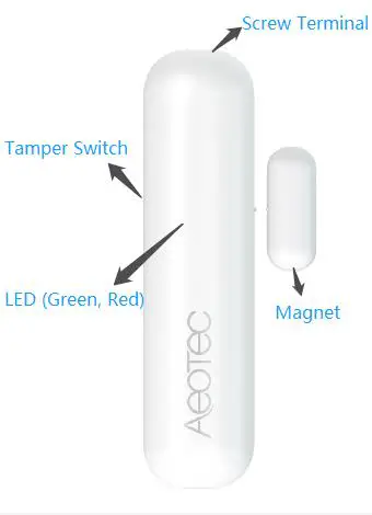
| Terminology | Description |
| tamper switch | Used for networking, resetting, and protecting the device. |
| Led (Green, Red) | Used for indicating the current state of the product. |
| Magnet | Change the sensor state via making the Magnet away or near from Main Sensor. |
| Screw Terminal | Used for the interconnection of external binary sensors as well as actuators and dry-contacts. |
SPECIFICATIONS
Structural
| Parameter | Value |
| Product Identifier | ZW012 |
| Dimensions | 28x95x35mm |
| Weight | Main Sensor: 20g Magnet Sensor: 3g |
| Color | White |
| Usage | For indoor use. |
| Operating Temperature | 32~104°F (0~40°C) |
| Relative Humidity | 8%~80% |
Hardware
| Buttons and Connectors | Tamper Button (x1), Magnet(x2) |
| Input Voltage | 3.0V Lithium battery |
| Battery Type | 1*1/2AA |
| Battery Included | Yes. 1pcs battery included. |
| Battery Required | Yes. 1pcs battery required. |
| Battery Info | Model: ER14250 1/2AA Capacity: 1200mAh Detachable: Yes Chargeable: No Endurance: 2 years |
| Working Current | 30mA |
| Standby Current | 5uA |
| Maximum Standby Power Consumption | 0.03mW |
| Maximum transmission | 5mW |
| Built-in Sensors | hall switch |
Software
| Parameter | Value |
| Wireless Technology | Z-Wave |
| Certification Type | Z-Wave Plus v2 Certification |
| Z-Wave SDK Version | 7.15.2 |
| Z-Wave Library Type | Enhanced 232 Slave |
| Z-Wave Role Type | Reporting Sleeping Slave[0x06] |
| Generic Product Type | GENERIC_TYPE_SENSOR_NOTIFICATION [0x07] |
| Specific Product Type | SPECIFIC_TYPE_NOTIFICATION_SENSOR [0x01] |
| Security Class | Non-Security, S2 Unauthenticated, and S2 Authenticated |
| SmartStart Compatible | Support. After powering on, SmartStart is auto activated. |
| Over The Air (OTA) | Support. Firmware can be updated via RF. |
| Multi-Channel Product | No |
| Association | Support. Refer to Section 4.7 Association Group Info. |
| Factory Reset | Support. Refer to Section 3.7 How to factory reset. |
| Power-down Memory | Support. All command settings will stay unchanged even power is down. |
| Sensor State Report | Support. Send out a notification via Group 1 when Magnet is away or near. |
| Control other product | Support. Control other Z-Wave products directly via Group 2 when Magnet is away or near |
QUICK START
Important safety information
Please read this manual carefully. Failure to follow the recommendations in this manual may be dangerous or may violate the law. The manufacturer, importer, distributor and seller shall not be liable for any loss or damage resulting from failure to comply with the instructions in this manual or any other material. Use this equipment only for its intended purpose. Follow the disposal instructions. Do not dispose of electronic equipment or batteries in a fire or near open heat sources.
Optimally placing the product
This is a secure Alarm Sensor. To run this device please insert fresh 1 * 1/2 AA batteries. Please make sure the internal battery is fully charged. The DSK for the S2 inclusion can be found inside the packaging of the sensor.
If your Z-Wave gateway supports SmartStart: scan the QR code on Door / Window Sensor 7 Pro using the gateway’s app. Your sensor will join your Z-Wave network automatically.
How to install the product
The sensor can be mounted either on the moving part or on the fixed part of a door or a window. Mounting can be accomplished either using the tape by peeling off the protection foil or using two screws with holes inside the battery compartment. If the tilt detection on a window (only normal windows, no roof windows) shall be used the sensor device must be placed on the moving part of the window and the magnet on the window frame.
The sensor comes with two types of magnets:
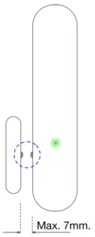
- The standard magnet is covered by a plastic part, mountable beside the sensor. Make sure the two indicating lines on the sensor enclosure and magnet are opposite to each other. The image on the righthand side shows the position of the magnet and sensor body.
- A slim naked magnet to be mounted behind the sensor in case the sensor body is placed on the side of a window.
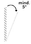
- To use the tilting function, the opening angle of the window must be at least 5°.

For German-style windows where the window sits on top of the window frame mounting on the side of the window is highly recommended. If no tilting detection is used, the sensor can be placed on any position of the door or the window. In case tilting detection is desired the sensor should be placed on the upper side of the window. 
How to add the product
The following will step you through by adding the product to your Z-Wave network.
- Open the housing.
- Remove the battery protection.
- Press the tamper on the side of the appliance three times quickly.
If your Z-Wave gateway supports SmartStart: scan the QR code on Door / Window Sensor 7 Pro using the gateway’s app. Your sensor will join your Z-Wave network automatically.
How to remove the product
- Open the housing.
- Press the tamper on the side of the appliance three times quickly.
How to manually trigger Wake Up
- A single click on the button will wake up the device.
- Repower on will wake up the device.
Note:
The Wake Up period starts when the node issues a Wake-Up Notification and it ends either 10 seconds after the last received/transmitted frame or at the reception of a Wake Up No More Information Command by the Wake-Up destination.
How to factory reset
This device also allows being reset without any involvement of a Z-Wave controller. This procedure should only be used when the primary controller is inoperable.
Once the Cover is removed and the tamper switch is tripped, push the tamper for 5 seconds until the RED LED blinks once. Then release the tamper and use it again for 5 seconds while the RED LED is blinking until the GREEN LED blinks once.
Safety Warning for Batteries
The product contains batteries. Please remove the batteries when the device is not used. Do not mix batteries of different charging levels or different brands.
Product Usage
Once installed the sensor will report “open” and “close” status changes to a central Z-Wave controller using notification commands. Additionally, the sensor can directly control other devices using association group 2. Using configuration commands the source of “open” and “close” events can be chosen between the internal magnet detector or external dry contact connected via the screw terminal. The device is protected by a tamper switch.
Tilt detection
The tilt detection allows reporting the way a window is opened. This is accomplished using the command class “binary sensor – tilt-type”. The tilt function has 3 modes (mode 1 by default):
Mode 0: turn off the tilt function
Mode 1: Enable tilt function. It needs to be used with magnets. In case the magnet is far away and the tilt angle of the product is greater than 5 degrees, the tilt event is triggered. In case the magnet is near, the tilt event is released.
Mode 2: Enable tilt function. It can be used alone, but need to identify the current installation location. When this mode is configured or powered on (mode 2), it will enter the identification mode and the green light will flash. The product needs to stand still for 3-8 seconds. If the recognition fails, the red light will be on, and the tilt function is not available. It needs to be recognized again. If the recognition is successful, the green light will be on. In case the tilt angle of the product is greater than 5 degrees, the tilt event is triggered. In case the tilt angle of the product is less than 5 degrees, the tilt event is released
Screw Terminal
The product must support the interconnection of external binary sensors as well as actuators and dry contacts. The product allows interconnection
with external sensors/actuators via 3-pin screw terminals with the following pinout:
- #1: Ground
- #2: Digital Input
- #3: VCC (direct battery supply)

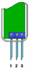
VCC + Ground terminals can be used to externally power the sensor with a 3.6V battery or special power adapter (which is not included in the scope of delivery). Digital + VCC is used to connect the external dry contact.
Link testing
When activated by configuration parameter #5 the device can perform a link test with device No.1. Double-clicking the tamper will start the process. As a result, the GREEN LED will blink two times in case of success and the RED LED will blink two times in case of failure.
SOFTWARE FUNCTION DEFINITION
User Behavior Interaction
| User behavior | Out of the Z-Wave network | In the Z-Wave network |
| Power OFF | cut the power. | Cut the power. |
| Power ON | Send Inclusion Requests for SmartStart Learn Mode. LED will flash red 5 times, which means it’s out of the Z-Wave network. if the gateway is adding the device succeeds through SmartStart, LEO will light up green for 2 seconds If Adding fails, LEO will off. The device will auto-reset and then activate SmartStart Learn Mode again. | Send Wake Up Notification. LED will become flash green once, and device will wake up for 15 seconds. |
| Make Magnet away or near | LED will flash red once. | Trigger Association function. Refer to Section 4.7 and 4.34 for details about the Association function. LED will flash red once. |
| Click tamper switch once | 1. LED will flash green once. LED will flash green one. 2. Exit Classic Inclusion Learn Mode: If the tamper switch is clicked again during the Classic inclusion Learn Mode, the Classic Learn Mode will exit. LEO will turn off. The device will auto-reset and then activate SmartStart Learn Mode again. | 1. Issue Wake Up Notification and stay awake for IS seconds unless put to sleep by Wake Up No More information frame. LED will flash green once. 2. Exit Classic exclusion Learn Mode: If the tamper switch is clicked again during the Classic exclusion Learn Mode, the Classic Learn Mode will exit. LEO will turn off. |
| Click tamper switch twice | Reserved | Start a link test with the controller (When activated by configuration parameter 53). If success, LEO will blink green two times If failure, LEO will blink red two times |
| Click tamper switch three times quickly | 1. Send Node info for Adeline. LED will blink green and red for the 30s until it is added to the network. If Adding succeeds, LEO will light up green for 2 seconds if Adding fails. LEO will turn off. The device will auto-reset and then activate SmartStart Learn Mode again. 2. Exit Classic Inclusion Learn Mode: If the tamper switch is clicked again during the Classic inclusion Learn Mode, the Classic Learn Mode will exit. LEO will turn off. The device will auto-reset and then activate SmartStart Learn Mode again. | 1. Send Node Info for Removing. LED will blink green and red for 30 seconds until it is removed from the network. if Removing succeeds, LEO will light up green for 2 seconds If Removing fails, LEO will turn off. 2. Exit Classic exclusion Learn Mode: if tamper switch is clicked again during the Classic exclusion Learn Mode, the Classic Learn Mode will exit. LEO will turn off. |
| Click tamper switch 5 times quickly | Reserved | Toggle configuration parameter 1 setting value from 0/1 |
| Press and hold tamper switch for 5 seconds | Factory Reset. push the tamper for 5 seconds until the RED LED blinks once. Then release tamper and push it again for 5 seconds while the RED LEO is blinking until the GREEN LED blinks once. | Factory Reset. push the tamper fors seconds until the RED LED blinks once. Then release tamper and push it again for 5 seconds while the RED LED is blinking until the GREEN LED blinks once. |
| The device will issue a Device Reset Locally Command via its Lifeline to notify the Lifeline destination that the device has been reset to its factory default state. And it will perform the reset operation regardless of whether or not the delivery of the Device Reset Locally Notification is successful. |
Supported Command Classes
| Command Class | Versio | Not added | Non-secure add | Securely 2 added Non-secure | Secure |
| ZWAVEPLUS_INFO | 2 | Support | Support | Support | |
| ASSOCIATION | 2 | Support | Support | Support | |
| MULTI_CHANNEL_ASSOCIATION | 3 | Support | Support | Support | |
| ASSOCIATION_GRP_INFO | 3 | Support | Support | Support | |
| TRANSPORT_SERVICE | 2 | Support | Support | Support | |
| VERSION | 3 | Support | Support | Support | |
| MANUFACTURER_SPECIFIC | 2 | Support | Support | Support | |
| DEVICE_RESET_LOCALLY | 1 | Support | Support | Support | |
| INDICATOR | 3 | Support | Support | Support | |
| POWERLEVEL | 1 | Support | Support | Support | |
| BATTERY | 1 | Support | Support | Support | |
| SENSOR_BINARY | 2 | Support | Support | Support | |
| CONFIGURATION | 4 | Support | Support | Support | |
| CENTRAL SCENE | 3 | Support | Support | Support | |
| SECURITY_2 | 1 | Support | Support | Support | |
| NOTIFICATION | 8 | Support | Support | Support | |
| WAKE_UP | 2 | Support | Support | Support | |
| SUPERVISION | 1 | Support | Support | Support | |
| FIRMWARE_UPDATE_MD | 5 | Support | Support | Support |
Basic Command Class mapping
Basic Command Class is not mapped to any of the supported command classes.
Z-Wave Plus Info
| Parameter | Value |
| Z-Wave Plus Version | 0x02 |
| Role Type | 0x06 [ZWAVEPLUS_INFO_REPORT_ROLE_TYPE_SLAVE_SLEEPING_REPORTING] |
| Node Type | 0x00 [ZWAVEPLUS_INFO_REPORT_NODE_TYPE_ZWAVEPLUS_NODE) |
| Installer Icon Type | 0x0C00 [ICON_TYPE_GENERIC_SENSOR_NOTIFICATION] |
| User Icon Type | 0x0C00 [ICON_TYPE_GENERIC_SENSOR_NOTIFICATION] |
Manufacturer Specific
| Parameter | Value |
| Manufacturer ID 1 | 0x03 |
| Manufacturer ID 2 | 0x71 |
| Product Type ID 1 | 0x00 [EU], 0x01 [US], 0x02 [AU] |
| Product Type ID 2 | 0x02 [PRODUCT_TYPE_ID_SENSOR] |
| Product ID 1 | 0x00 |
| Product ID 2 | 0x0C |
Version
| Parameter | Value |
| Z-Wave Protocol Library Type | 0x03 |
| Z-Wave Protocol Version | 0x07 |
| Z-Wave Protocol SubVersion | 0x0C |
| Firmware 0 Version | 0x01 [Z-Wave Chip Firmware Version] |
| Firmware 0 SubVersion | 0x00 [Z-Wave Chip Firmware Sub Version] |
| Hardware Version | 0x01 |
| Number of firmware targets | 0x00 |
Association Group Info
Root product
| ID | Name | Node count | Profile | Function |
| 1 | Lifeline | 5 | General: Lifeline (0x0001) | Product Reset Locally Notification: Issued when Factory Reset is performed. Battery Report: Issued when battery becomes low. Sensor Binary Report: Issued when tilt angle is changed Issued when sensor state is changed. Notification Report [Type=0x06; Event=0x16]: Issued when sensor state is changed to be Open Status. Notification Report [Type=0x06; Event=0x17]: Issued when sensor state is changed to be Close Status. Notification Report [Type=0x07; Event=0x03]: Issued when tamper is tripped Central Scene Notification: Issued when the external dry contact is activated |
| 2 | Control | 5 | Control: Key01 (0x2001) | Basic Set: Control devices when a magnet or external dry contacts trips |
| 3 | Alarm | 5 | Notification: Access Control (0x7106) | Notification Report: Sends out alarm message when a magnet or external dry sensor trips |
| 4 | Tamper | 5 | Notification: home Security (0x7107) | Notification Report: Sends alarm messages when tamper is tripped |
| 5 | Tilting | 5 | Control: Key02 (0x2002) | Basic Set: Control devices when tilting sensor trips |
Notification
| Notification Type | Notification Events | Description | ||
| Access Control | 0x06 | Window/Door is open | 0x16 | Open Status. |
| Window/Door is closed | 0x17 | Close Status. | ||
| Home Security | 0x07 | Tamper Removed | 0x03 | Tamper removed |
| 0x00 | State idle | 0x00 | Going to idle | |
Binary Sensor
| Sensor Type | Sensor Value | Description | |
| Door/Window | 0x0A | 0x00 / 0xFF | Door/Window State |
| Tilt | 0x0B | 0x00 / 0xFF | tilt event |
CENTRAL SCENE
When activated by configuration parameter #14 the device can perform as a scene controller. Digital + VCC is used to connect the scene button. The external dry contact will then act as a scene controller with a total of 7 scenes that can be activated:
- 1 – Contact Pressed 1 time
- 2 – Contact Pressed 2 time
- 3 – Contact Pressed 3 time
- 4 – Contact Pressed 4 time
- 5 – Contact Pressed 5 time
- 6 – Contact held down
- 7 – Contact released
Slow Refresh = 0, A new Key Held Down notification will be sent every 200ms until the key is released.
Wake Up
| Parameter | Value | Time |
| Min Wake Up Interval Seconds | 0x000E10 | 3600s [1 hour] |
| Max Wake Up Interval Seconds | 0xEFF100 | 15724800s |
| Default Wake Up Interval Seconds | 0x093A80 | 604800s [1 week] |
| Wake Up Interval Step Seconds | 0x0000F0 | 240s [4 minutes] |
Battery
- The 2.90V or more battery voltage corresponds to 100% battery level, and 2. 60V or less corresponds to 0%.
- If send Battery Get to the device, it will issue Battery Report with battery level to the requester when waked up.
- If waked up or power on, it will detect battery level, and issue Battery Report 0xFF via Lifeline when the battery level is less than the value of configuration parameter 23.
- If the battery level is less than the value of configuration parameter 23 , LED will flash red 3 times for each wake-up.
Indicator
| Indicator ID | Property ID | ||
| Node Identify (Green Led) | 0x50 | On Off Period | 0x03 |
| On Off Cycles | 0x04 | ||
| On-time within an On/Off period | 0x05 |
FCC Caution.
This device complies with part 15 of the FCC Rules. Operation is subject to the following two conditions:
- This device may not cause harmful interference
- this device must accept any interference received, including interference that may cause undesired operation.
Any Changes or modifications not expressly approved by the party responsible for compliance could void the user’s authority to operate the equipment.
Note: This equipment has been tested and found to comply with the limits for a Class B digital device, pursuant to part 15 of the FCC Rules. These limits are designed to provide reasonable protection against harmful interference in a residential installation. This equipment generates uses and can radiate radio frequency energy and, if not installed and used in accordance with the instructions, may cause harmful interference to radio communications. However, there is no guarantee that interference will not occur in a particular installation. If this equipment does cause harmful interference to radio or television reception, which can be determined by turning the equipment off and on, the user is encouraged to try to correct the interference by one or more of the following measures:
- Reorient or relocate the receiving antenna.
- Increase the separation between the equipment and receiver.
- Connect the equipment into an outlet on a circuit different from that to which the receiver is connected.
- Consult the dealer or an experienced radio/TV technician for help.


