![]()
AOI UH-EM5III UNDERWATER HOUSING
GENERAL GUIDE
Thank you for your purchase of an AOI product. Please read this general guide prior to using the housing. It will provide an overview of how this product can be used for optimal performance. For additional information, please consult your local dealer or write to [email protected]
Items Included in the package
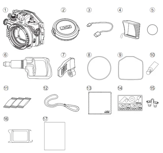
| 1. AOI UH-EM5III Housing Body 2. Body Cap / Storage Box for OM-D 3. Mount Housing 4. USB Type-C Charging Cable 5. Monitor Hood 6. Spare O-Ring for Vacuum Valve Protection Cap x1pc 7. Vacuum Pump (AOI VP-01) 8. Extended Shutter Release Lever 9. Spare Main Seal O-Ring x1pc. 10. Spare Secondary Seal Ring x1pc | 11. Silicone Grease (AOI SIGR-5) 12. Silica Gel (AOI SIGE-3) x3pcs 13 . Lanyard 14. AOI Lens Cleaning Micro Fiber Cloth 15. AOI Logo Sticker 16. Fiber Optic Cable Port Plug x2pcs AOI O-Ring Remover / White Balance Card (AOI ORR-01) 17.AOI UH-EM5III General Guide |
Names of the Parts
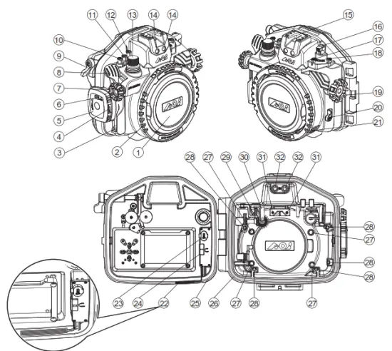
| 1. Body Cap (Storage Box) 2. Port Locking Ring 3. Lanyard Eyelet 4. Cam Lock Release 5. Cam Lock 6. Security Lock 7. Front Dial 8. Shutter Release Lever 9. AEL/AFL Button Lever 10. 11. 12. Mode Dial | 13. Vacuum Valve 14. Fiber Optic Cable Ports 15. Cold Shoe Mount 16. Camera ON/OFF Lever 17. 18. 19. Gear Control Knob 20. Lever 21. Security Lock for Port Locking Ring 22. Wet Detection Strip 23. USB Type-C Charging Port | 24. Power ON/OFF Switch for 25. Vacuum Analysation and Wet Detection System (VWS) 25. Main Seal O-ring 26. Secondary Seal Ring 27. Camera Front Stoppers 28. amera Positioning Bumpers 29. Bridge Gear for Lens Gear 30. Camera ON/OFF Actuation Lever 31. Camera Top Stoppers 32. LED Flash Trigger Ports |
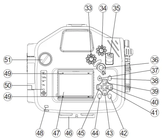
| 33. Mode Dial 34. Rear Dial 35. ISO Button36 . AEL/ AFL/ Lever37. menu button38. INFO Button39. Arrow 40. 41. OK Button42. | 43. 44.  Button Button45. 46. 1/4”-20 (x3) Tripod Sockets 47. LCD Monitor Window 48. LCD Hood String Eyelet 49. LCD Monitor Hood Rail 50. Vacuum Analyzation & Wet Detection System Status Indicator 51. Spare M16 port |
Installing a camera in the housing
a. Before use, ensure the camera (Olympus OM-D E-M5 Mark III) and camera lens are compatible with the housing, lens port and lens gear. 
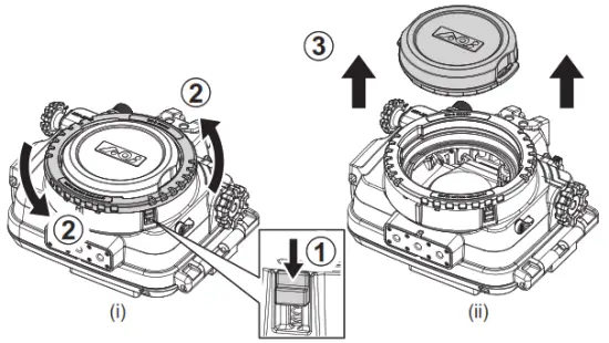
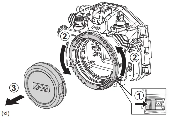
b. Slide down the Security Lock for the Port Locking Ring and rotate the Port Locking Ring counter-clockwise (fig.i).
Align the Port Locking Ring (two) cut-outs with the Body Cap’s cut-outs, remove by lifting Body Cap straight up (fig.ii).
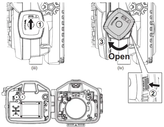
c. Unlock the Security Lock on the Cam Lock (fig.iii). Press down the Cam Lock Release and rotate the Cam Lock clockwise at the same time (fig.iv). Rotate the Cam Lock until
the Rear Cover is fully separated from the Cam Lock.
 d. Turn on the Vacuum Analysation & Wet Detection System (VWS). If its battery power is low, the Signal Indicator will blink rapidly (4 times/sec), connect the supplied USB
Type-C Charging cable to the USB Type-C Port in the inner side of the Rear Cover and the other end to a USB Charger DC 5V, minimum 0.5A (not supplied). It will take
approx. 1.5 hours to fully charge the battery. Table 1 below shows the status of battery charging and the corresponding light of the Signal Indicator. Battery operation time per charge is approx. 100 hours.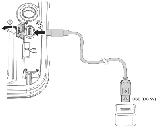
Table 1
| Signal Indicator | Indication | Next Action |
| Fast Blinking BLUE light (4 times/sec) | Charge is required | Connect it to a USB charger for charging |
| Fast Blinking GREEN light | Charging in progress | Continue charging |
| Still GREEN light | Charging is completed | Remove from a USB charger and stop charging |
f. Turn off the camera before installing it into the housing. Remove all camera accessories such as Layard, Lens Filter or Hand Grip., etc.
g. Pull up the Camera ON/OFF Actuation Lever up before you install the camera into the housing (fig. vii-a).
h. Return the Camera Monitor back to its original position with the display facing outside and make sure the Camera Strap Eyelets are folded down against the camera body
(fig. vii-b). Load the camera into the housing gently and do not hold the camera by the Monitor Screen while inserting.
i. After the camera is properly loaded, push down the Camera ON/OFF Actuation Lever and engage with the camera ON/OFF Lever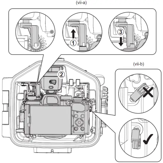
j.Turn on the power of the Vacuum Analysation and Wet Detection System (VWS) (fig. viii).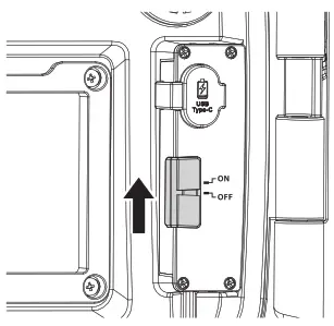
k.Before closing the housing, ensure the camera is positioned properly against the Camera Positioning Bumpers in the front of the housing. Check that the Main Seal O-ring and Secondary Seal Ring are clean, intact, and properly positioned. There are no obstacles such as the lanyard or strips preventing the secure closure of the housing.
i. Close the Housing Rear Cover by rotating the Cam Lock counter-clockwise until a “Click” sound is heard (fig.ix). If you encounter resistance, clear obstacles before continuing.
m. Switch the Security Lock on the Cam Lock to the “LOCK” position in order to prevent Cam Lock from opening accidentally (fig.x).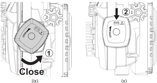 n. Once the camera is installed and the housing is closed, turn on the power of the camera and make sure all housing controls and lens gear function properly. If you prepare to
use an external flashlight, check that the Olympus Flash FL-LM3 or AOI LED Optical Strobe Trigger STR-04 (optional accessory) is functioning with the external slave
strobe(s).
Installing Lens Port in the housing
a. Remove Body Cap.
b. Installing an OM-D Mount Port in the housing body.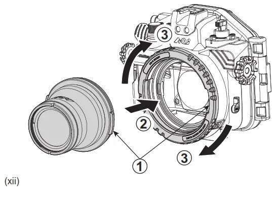
c. Installing PEN Mount Port with the AOI AD-LP-01 (Adapter for PEN Port to OM-D Port) in the housing body.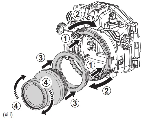
d. Installing OM-D Mount Port with AOI ER-OD_OD-22 ( Extension Ring 22mm OM-D Port to OM-D Mount Housing) in the housing.\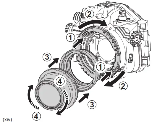 For more information about AOI UH-EM5III Expansion Pathway and OM-D Mount Lens Ports System, please download the OM-D PORTS CHART from www.aoi-uw.com
Pre-checking before Diving
1. Perform Vacuum Analyzation
a. Power on the Vacuum Analysation and Wet Detection System (VWS), if the Signal An indicator shows Blinking BLUE (1 time/sec), which means the Vacuum Analysis and
The wet Detection Sensor is on standby mode. Close the Rear Cover according to the steps described in “Installing camera into the housing”.
b. Take off the Protection Cap from the Vacuum Valve and connect the Vacuum Pump to the Vacuum Valve Tip. Pull and Release the Vacuum Pump handle gently and
repeatedly for Vacuum Pumping. During the Vacuum Pumping process, check carefully for changes in colour on the Signal Indicator.
1. Perform Vacuum Analyzation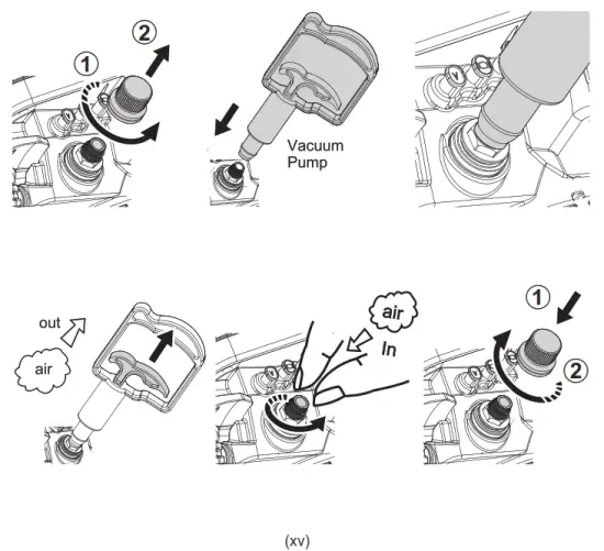
c. Colour Codes Indication:
Fast Blinking YELLOW
Internal pressure has started to drop. Continue to pump.
Slow Blinking YELLOW
The internal vacuum level is close to the desired value. Slow down pumping.
Still YELLOW
The internal vacuum level has been reached. Stop pumping and the Vacuum Analyzation Process will start automatically.
Blinking alternate YELLOW & RED
The internal vacuum level is above the desired value. Stop pumping and carefully release air by gently twisting the Vacuum Release Tip counter-clockwise slightly
until the Signal Indicator turns to Still YELLOW. If too much air is released from the housing, the Signal Indicator will change back to Blinking YELLOW again.
Resume vacuum pumping until Signal Indicator turns to Still YELLOW.
d. The Vacuum Analysation Process will start automatically once the Signal Indicator turns Still YELLOW. Disconnect the Vacuum Pump from the Vacuum Valve carefully and then put back Protection Cap to the Vacuum Valve. Do not move or shake the housing or put the housing under the sun when the analysis process has started.
e. The Vacuum Analyzation Process takes approx.4 minutes. Once the process is completed, the Signal Indicator will turn either RED or GREEN, depending on the result:
Blinking GREEN – Vacuum Analyzation passed and Housing is ready to go into the water.
Blinking RED – Vacuum Analyzation failed and inspection for leak is required.
f. In case of a significant air leakage detected anytime during/after the Vacuum Analyzation Process, the Signal Indicator will turn Blinking RED.
g. Below (Table 2) is the summary of Signal Indicator Colour Codes Indication.
Table 2
| Signal Indicator | Indication | Next Action |
| Slow Blinking BLUE (1 time/sec) | Ready for Vacuum analyzation | Vacuum Pumping |
| Blinking YELLOW | Vacuum below the desired level | Continue pumping |
| Blinking Altern YELLOW – RED | Vacuum above the desired level | Twist the Vacuum Release Tip counter-clockwise |
| Still YELLOW | Vacuum analysis in progress | Wait for 4 minutes for vacuum analyzation |
| Slow Blinking GREEN | The vacuum analyzation test has Passed | Ready for going into water |
| Blinking RED | Vacuum analysis test has Failed | Inspect the housing for any potential air leakage sources |
| Steady RED with audible alarm | Wet Sensor Strip detects water droplets or moisture | Inspect the housing for any potential water leakage sources |
2. Perform Water Leakage Test
Once Vacuum Analysation is completed successfully and Vacuum Valve Protection Cap is secured, review the housing further by checking for water leakage. Submerge it in a shallow tub of water or rinse tank. While submerged, activate all the control buttons, control switches, and control knobs in order to have a dynamic test to prove all the sealed moving parts are water sealed properly. If there is no water droplet observed inside the housing after Underwater Dynamic Test, it means the housing is fully watertight. If water leaks into the housing, the water droplets will be detected by the Wet Sensor Strip located in the lowest part of the housing. Signal Indicator will turn Still RED and audible alarm “BEEP-BEEP-BEEP” will be heard.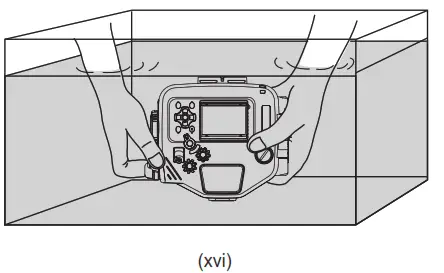
Using the Housing and Camera after testing passed
a. Please ensure that the Vacuum Valve Cap is in place and completely closed.
b. When using the housing, make sure that it is properly secured to you and accessories are properly secured to the housing.
c. Do not exceed the housing maximum depth rating of 60 meters (200 ft.)
d. If the Wet Detection alarm is triggered during use, it means water has entered the housing. If that happens, try to position the housing lens port facing down and exit the
water safely in accordance with diving procedures and regulations. Upon returning to land, remove the camera from the housing. If only a few droplets of seawater entered
the housing, thoroughly wipe off the seawater droplets with a moist towel and dry the inside of the housing thoroughly with tissue paper.
e. If seawater leaks into the housing and the Multi-control Device is flooded, take out the camera, rinse the housing cavity thoroughly with running fresh water for a few minutes. Then, dry the housing cavity completely and bring it to your local dealer for servicing immediately.
Connecting the Fiber Optic Cable
a. You can install Olympus Flash FL-LM3 or AOI LED Optical Strobe Trigger STR-04 on the camera hot shoe and use either one for the external Slave Flash(es) triggering.
b. This housing is equipped with two Fiber Optic Cable Ports and they are compatible with AOI Fiber Optic Cables with SS cable plug or other fiber optic brands using the
standard of Sea & Sea plug.
c. Insert one end of the fiber optic cable into the Fiber Optic Cable Port of the housing (fig. xvii) and then insert the other end into the fiber optic cable port on the external
flash or strobe.
IMPORTANT:
a. Check the compatibility of the Filter Optic Cable and multicore fiber optic cable is recommended and preferable.
b. When you use Olympus Flash FL-LM3 and use only one side of the Fiber Optic Cable Port, the other blank out Fiber Optic Cable Port must be closed by a Fiber Optic Plug
(included in housing accessories). Otherwise, the flashlight will emit out from the blank
c.Rinse the Fiber Optical Cable Ports with running fresh water after every use, then let it dry naturally. Do not dry inside of the ports with any tool, this may result in scratches
and reduce the capacity of the optical signal transfer.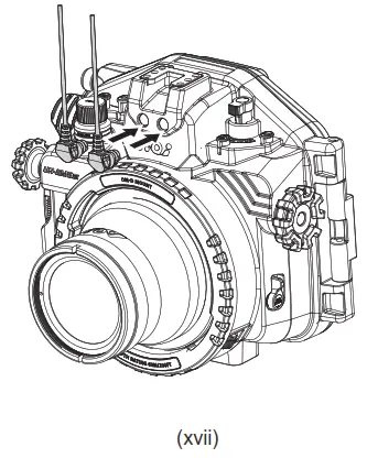
Care and Maintenance
a. Rinse the housing exterior thoroughly with running fresh water after every use.
Depress buttons and rotate knobs/dials repeatedly in freshwater to eliminate trapped saltwater or debris. Dry the housing and Lens Port with a soft, clean cloth to avoid
water spotting and damage.
b. To clean the Lens Port Glass, use a mild soap solution or lens cleaner. Do not rinse the inside of port glass. Do not use alcohol or window cleaner on the Lens Port Glass.
c. In order to better inspect, position, clean or lubricate the Housing Main Seal O-ring or Lens Port O-rings, carefully remove the required O-ring by using the provided AOI
O-Ring Remover/White Balance Card.
d. Clean the O-ring and the O-ring groove by using a microfiber cloth only. Use AOI
O-Ring Remover/White Balance Card to clean the O-Ring groove. Do not use cleaning substances other than freshwater. Remove sand, dirt, hair or fibers that can
prevent a proper housing seal.
e. To lubricate O-rings, apply a small amount of silicone grease (AOI SIGR-5) on your fingertips, gently pull the O-ring through the fingertips. This will lightly coat the entire
O-ring with silicone grease. Only use the AOI Silicone Grease supplied or those approved by AOI. Using other brands of silicone grease may damage the O-ring. Do
not over-stretch the O-ring.
f. Do not leave the camera and housing in direct sunlight for prolonged periods. Heat may damage the camera and housing.
g. Dry well and remove the camera prior to travel and storage.
h. Store the housing in a cool and dry place.
IMPORTANT:
Wipe the housing dry and keep water away prior to opening the housing.
Do not allow water to be in contact with the interior of the housing. This will cause irreparable damage to the Vacuum Analysation and Wet Detection System (VWS)
and other electronic/electrical components!
Specifications
| Model Number | AOI UH-EM5III | |
| Housing Colour | AOI UH-EM5III-BLK | AOI UH-EM5III-CAM |
| Black | Camo Blue | |
| Compatible Camera Model | Olympus OM-D E-M5 Mark III | |
| Main Material | Housing Body: Polycarbonate | |
| Depth Rating | 60 Meters (200 ft.) | |
| Operating Environment | Operation : 0 C ~ 40 C (32 F ~ 104 F) | |
| Storage : -20 C ~ 60 C (-4 F ~ 140 F) | ||
| Battery for Vacuum Analysation and Wet Detection System (VWS) | Built-in Rechargeable Lithium Polymer Battery (3.7V) | |
| Charging : USB Charger DC 5V, 0.5A (not included) Approx. 1.5 hours for a full charge | ||
| Battery Operation Time : Approx. 100 hours | ||
| Dimensions | Approx. 206.20mm (W) x 181.70mm (H) x 113.55mm (D) | |
| Weight | Approx. 1340g (LCD Monitor Hood and Lanyard included, camera and accessories not included) | |
![]()
AOI is a registered trademark of AOI Ltd. All rights reserved.
All other trademarks are the property of their respective owners.
www.aoi-uw.com
Made in China
6E01015A-00001


