![]()
Installation Guide
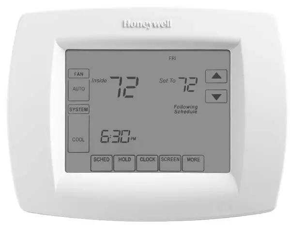
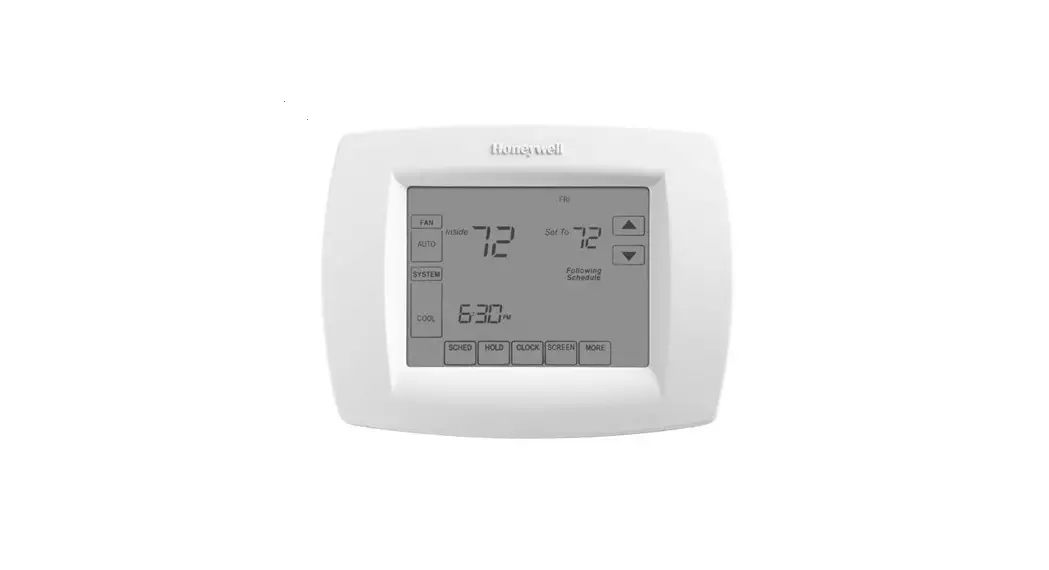
VisionPRO ® TH8000 Series
Touch-screen Programmable Thermostat
VisionPRO TH8000 Series Touch Screen Programmable Thermostat
This manual covers the following models
- TH8110U: For 1 Heat/1 Cool systems
- TH8320U: For up to 3 Heat/2 Cool systems
- TH8321U: For up to 3 Heat/2 Cool systems with dehumidification (Pull thermostat from wallplate and turn over to find model number)
System Types
- Gas, oil, or electric heat with air conditioning
- Warm air, hot water, highefficiency furnaces, heat pumps, steam, gravity
- Heat only — two-wire systems, power to open and close zone valves (Series 20), and normally open zone valves
- Heat only with fan
- Cool only
- 750 mV heating systems
This thermostat contains a Lithium battery which may contain Perchlorate material. Perchlorate Material–special handling may apply, See www.dtsc.ca.gov/hazardouswaste/perchlorate
Need Help?
For assistance with this product please visit http://customer.honeywell.com
or call Honeywell Customer Care toll-free at 1-800-468-1502
® U.S. Registered Trademark.
Copyright © 2012 Honeywell International Inc.
All rights reserved.

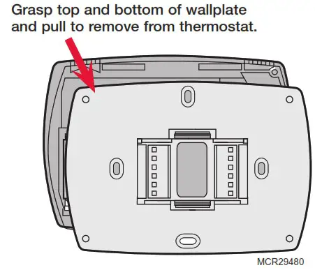
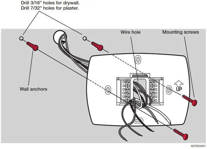
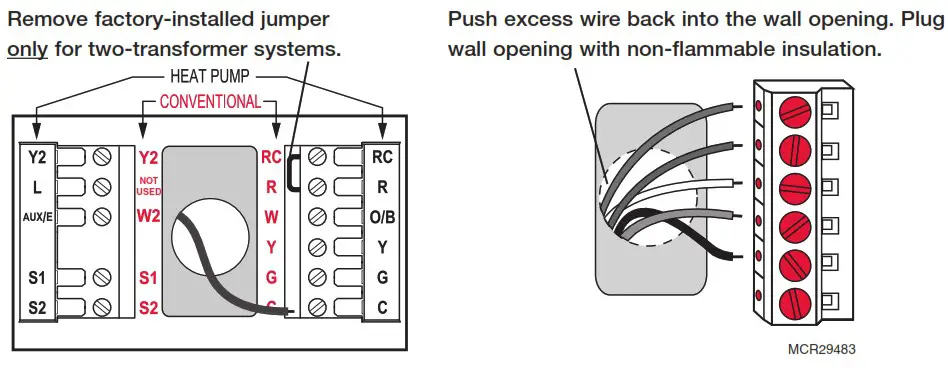
Wallplate installation
- Separate wallplate from thermostat.
- Mount wallplate as shown below.
Must be installed by a trained, experienced technician
• Read these instructions carefully. Failure to follow these instructions can damage the product or cause a hazardous condition.
![]() CAUTION: ELECTRICAL HAZARD
CAUTION: ELECTRICAL HAZARD
Can cause electrical shock or equipment damage. Disconnect power before beginning installation.![]() MERCURY NOTICE
MERCURY NOTICE
If this product is replacing a control that contains mercury in a sealed tube, do not place the old control in the trash. Contact your local waste management authority for instructions regarding recycling and proper disposal.
Power options
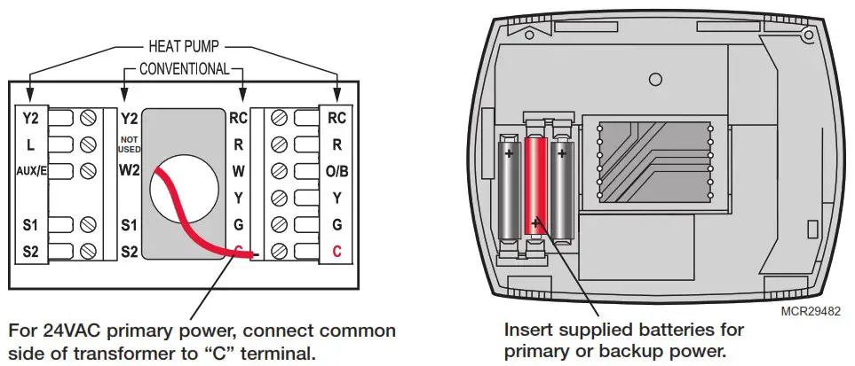
Wiring
Terminal Designations Shaded areas below apply only to TH8320/TH8321.
Conventional Terminal Letters:
R Heating power. Connect to secondary side of heating system transformer.
Rc Cooling power. Connect to secondary side of cooling system transformer.
C Common wire from secondary side of cooling transformer (if 2 transformers).
W 1st stage heat relay.
W2 2nd stage heat relay.
Y 1st stage compressor contactor.
Y2 2nd stage compressor contactor.
G Fan relay.
S1 Optional outdoor or remote sensor.
S2 Optional outdoor or remote sensor.
Heat Pump Terminal Letters:
R Heating power. Connect to secondary side of heating system transformer.
Rc Cooling power. Connect to secondary side of cooling system transformer.
C Common wire from secondary side of cooling system transformer.
Y 1st stage compressor contactor.
Y2 2nd stage compressor contactor.
Aux/E Auxiliary/Emergency heat relay.
G Fan relay.
L Heat pump reset (powered continuously when System is set to Em Heat; system monitor when set to Heat, Cool or Off).
O/B Changeover valve for heat pumps.
S1 Optional outdoor or remote sensor.
S2 Optional outdoor or remote sensor.
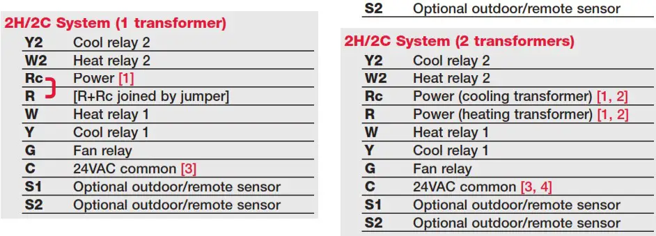
Wiring guide—conventional systems
Shaded areas below apply only to TH8320/TH8321.
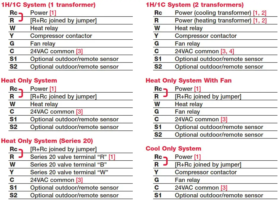
See [notes] below
[1] Power supply. Provide disconnect means and overload protection as required.
[2] Remove jumper for 2-transformer systems.
[3] Optional 24VAC common connection.
[4] Common connection must come from cooling transformer.
Wiring guide—heat pump systems
Shaded areas below apply only to TH8320/TH8321.
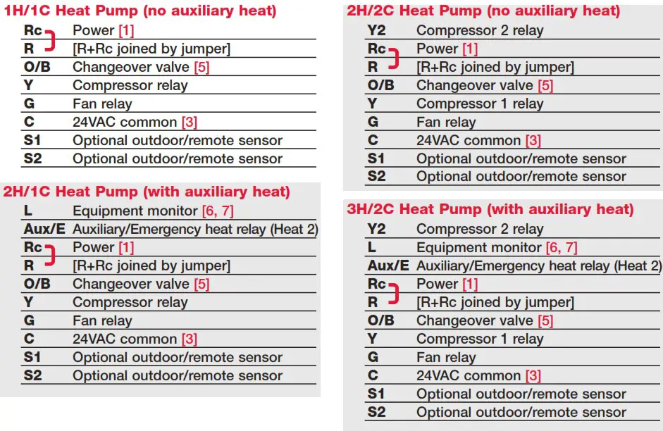
See [notes] below
[1] Power supply. Provide disconnect means and overload protection as required.
[3] Optional 24VAC common connection.
[5] O/B set to control as either O or B in installer setup.
[6] If L terminal is used, 24VAC common (terminal C) must be connected.
[7] Heat pump reset (powered continuously when thermostat is set to Em. Heat; system monitor when set to Heat, Cool, or Off).
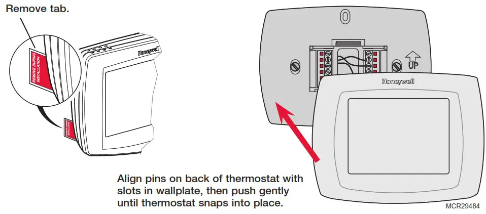
Remove tab and mount thermostat
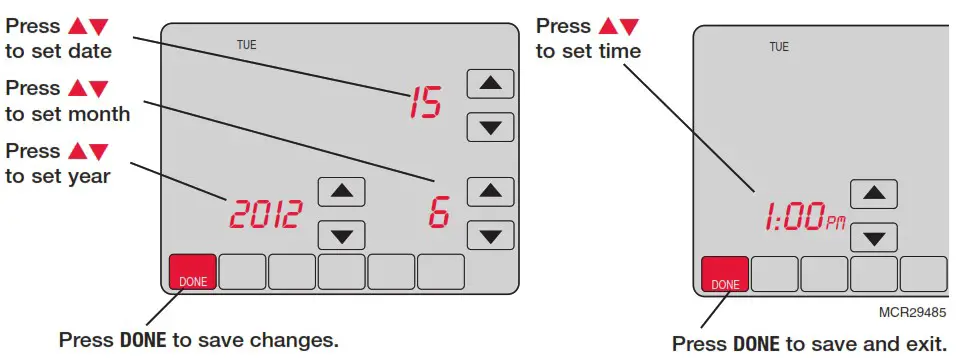
Set date and time
Installer setup
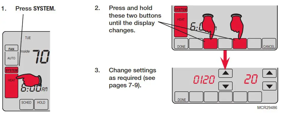
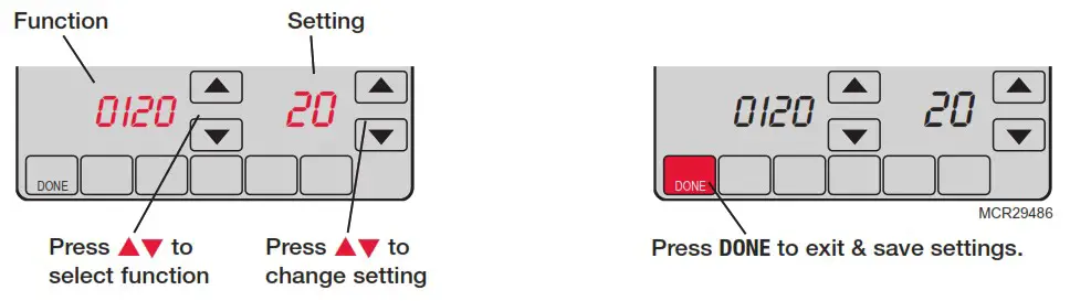
Setup functions
Settings & Options (factory default in bold)
Shaded areas below apply only to TH8320/TH8321.
| 0120 | Year (first two digits) | 20 (2001-2099) 21 (2100-2178) |
| 0130 | Year (second two digits) | 12 (2012) [Other options: 00-99] |
| 0140 | Month | 6 [Other options: 1-12] |
| 0150 | Date | 15 [Other options: 1-31] |
| 0160 | Schedule format | 4 7-day programming 0 Non-programmable |
| 0170 | System type | 1 1 heat/1 cool conventional 2 1 heat/1 cool heat pump (no aux. heat) 3 Heat only (2-wire systems) 4 Heat only with fan 5 Hot water Series 20 system (power to open & close zone valves/normally open zone valves) 6 Cool only 7 2 heat/1 cool heat pump (with aux. heat) 8 2 heat/2 cool multistage conventional 9 2 heat/1 cool multistage conventional 10 1 heat/2 cool multistage conventional 11 2 heat/2 cool heat pump (no aux. heat) 12 3 heat/2 cool heat pump (with aux. heat) |
| 0180 | Fan control (heating) | 0 Gas/Oil heat (equipment controls heating fan) 1 Electric furnace (thermostat controls heating fan) |
| 0190 | Changeover valve (O/B terminal) | 0 O/B terminal controls valve in cooling 1 O/B terminal controls valve in heating |
| 0200 | Auxiliary heat | 0 Electric backup heat 1 Fossil fuel backup heat |
| 0210 | External fossil fuel kit | 1 External fossil fuel kit controls backup heat 0 Thermostat controls backup heat (outdoor sensor required) |
| 0220 | 1st stage com- pressor cycle rate | 3 Recommended for most compressors [Other options: 1, 2, 4, 5 or 6 CPH] |
| 0230 | 2nd stage com- pressor cycle rate | 3 Recommended for most compressors [Other options: 1, 2, 4, 5 or 6 CPH] |
| 0240 | First stage heat cycle rate (CPH=cycles per hour) | 5 Gas or oil furnaces of less than 90% efficiency 1 Steam or gravity systems 3 Hot water systems & furnaces of 90%+ efficiency 9 Electric furnaces [Other options: 2, 4, 6, 7, 8, 10, 11, 12 CPH] |
| 0250 | Second stage heat cycle rate (CPH) | 5 Gas or oil furnaces of less than 90% efficiency 1 Steam or gravity systems 3 Hot water systems & furnaces of 90%+ efficiency 9 Electric furnaces [Other options: 2, 4, 6, 7, 8, 10, 11, 12 CPH] |
| 0260 | Third stage heat cycle rate (CPH) | 9 Electric auxiliary heat or electric furnaces 1 Steam or gravity systems 3 Hot water systems & furnaces of 90%+ efficiency 5 Gas or oil furnaces of less than 90% efficiency [Other options: 2, 4, 6, 7, 8, 10, 11, 12 CPH] |
| 0280 | Backlight | 0 Backlight on for approx. 8 seconds after keypress 1 Backlight always on low intensity, full bright after keypress (requires 24VAC connection) |
| 0300 | Manual/Auto changeover | 0 Manual changeover (Heat/Cool/Off) 1 Automatic changeover (Heat/Cool/Auto/Off) |
| 0310 | Auto changeover deadband | 3 Heat/cool temperature 3°F apart (1.5°C) ** See page 11 [Other options: 2-9 (2°F to 9°F/1.5 °C to 5°C)] |
| 0320 | Temperature display | 0 Fahrenheit 1 Celsius |
| 0330 | Daylight savings | 2 Auto-change to daylight savings time (2007 and beyond, for areas that use the new 2007 DST calendar) 1 Auto-change to daylight savings time (through 2006, and for areas that do not use the new 2007 DST calendar) 0 Daylight savings time is turned off |
| 0340 | Remote sensor | 0 No remote sensor 1 Outdoor sensor (display only) 2 Outdoor control sensor (select heat pumps) ** See page 11 3 Indoor sensor |
| 0350 | Heat pump compressor lockout | 0 No heat pump compressor lockout [Other options: 15, 20, 25, 30, 35, 40°F (-9.5°C to 7°C)] |
| 0360 | Heat pump auxiliary lockout | 0 No heat pump auxiliary lockout [Other options: 40, 45, 50, 55, 60°F (4.5°C to 15.5°C)] |
| 0380 | Dehumidification control | 0 No dehumidification control 1 Thermostat controls dehumidification with air conditioner ** See page 11 |
| 0500 | Furnace filter change reminder | 0 Off 1 10-day run time (about 1 month) 2 30-day run time (about 3 months) 3 60-day run time (about 6 months) 4 90-day run time (about 9 months) 5 120-day run time (about 1 year) 6 365-day run time (about 3 years) |
| 0510 | Humidifier pad change reminder | 0 Off 1 90 calendar days 2 180 calendar days 3 365 calendar days |
| 0520 | UV lamp change reminder | 0 Off 1 365 calendar days |
| 0530 | Adaptive Intelligent Recovery™ | 1 On ** See page 11 0 Off |
| 0540 | Program periods | 4 4 program periods (Wake, Leave, Return, Sleep) 2 2 program periods (Wake, Sleep) |
| 0580 | Compressor protection | 5 5 minute compressor off time ** See page 11 [Other options: 0, 1, 2, 3 or 4-minute off time] |
| 0600 | Heat temperature range stop | 90 Max. heat temperature setting is 90°F (32°C) [Other options: 40-89°F (4.5°C to 32°C)] |
| 0610 | Cool temperature range stop | 50 Min. cool temperature setting is 50°F (10°C) [Other options: 51-99°F (10.5°C to 37°C)] |
| 0640 | Clock format | 12 12-hour time (i.e., “3:30 pm”) 24 24-hour time (i.e., “15:30”) |
| 0650 | Extended fan timer (heat) | 0 Off 90 Fan runs for 90 seconds after call for heat ends |
| 0660 | Extended fan timer (cool) | 0 Off 90 Fan runs for 90 seconds after call for cooling ends |
| 0670 | Keypad lock | 0 Keypad unlocked (fully functional) 1 Partially locked (access to temperature settings only) 2 Fully locked |
| 0680 | Heat temperature control | 2 Standard temperature control (recommended) 1 Choose if room is warmer than set temperature 3 Choose if room does not reach set temperature |
| 0690 | Cool temperature control | 2 Standard temperature control (recommended) 1 Choose if room is cooler than set temperature 3 Choose if room does not reach set temperature |
| 0700 | Temperature display offset | 0 Thermostat displays actual room temperature [Other options: -3, -2, -1, 1, 2, 3°F offset (-1.5°C to 1.5°C) |
| 0710 | RESET | 0 No reset 1 Reset installer options & program schedule to factory default (only date and time settings are retained) |
Installer system test
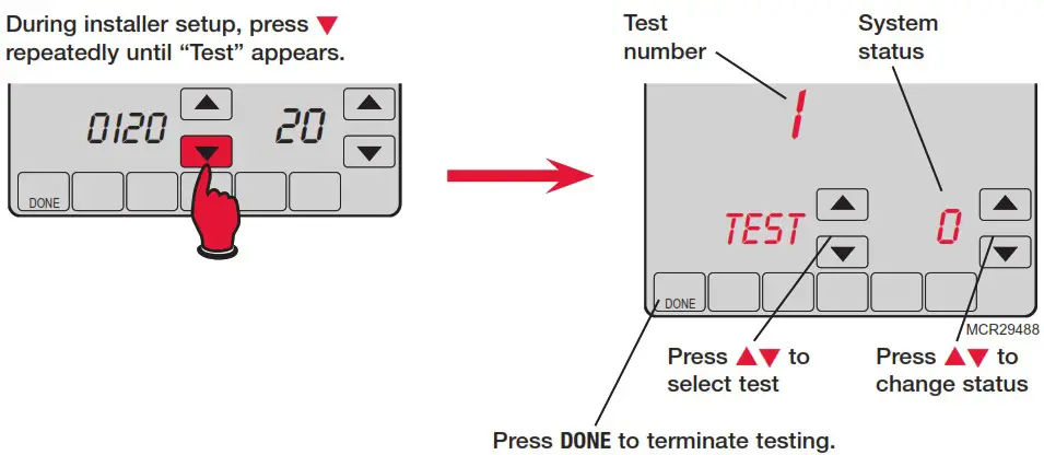
Shaded areas below apply only to TH8320/TH8321.
| System test | System status |
| 1 Cooling system | 0 Compressor and fan turn off 1 Compressor and fan turn on 2 Second stage compressor turns on |
| 2 Fan system | 0 Fan turns off 1 Fan turns on |
| 3 Heating system | 0 Heat and fan turn off 1 Heat turns on (fan on if Function 0170 is set for heat pump, or if Function 0180 is set to “1”) ** See page 6 2 Second stage heat turns on 3 Third stage heat turns on |
| 4 Emergency heating system | 0 Heat and fan turn off 1 Heat and fan turn on |
![]() CAUTION: EQUIPMENT DAMAGE HAZARD. Compressor protection is bypassed during testing. To prevent equipment damage, avoid cycling the compressor quickly.
CAUTION: EQUIPMENT DAMAGE HAZARD. Compressor protection is bypassed during testing. To prevent equipment damage, avoid cycling the compressor quickly.
Special functions
Shaded areas below apply only to TH8320/TH8321.
Auto Changeover (Setup Function 0300): When set to Auto, the thermostat automatically selects heating or cooling depending on the indoor temperature. Heat and cool settings must be at least 2 degrees apart. If function 0380 is set to On, the heat and cool settings must be at least 5 degrees apart.
Remote Sensor (Setup Function 0340): If an optional outdoor sensor is installed, the thermostat can display the outside temperature. If an optional remote indoor sensor is installed, the thermostat will display the temperature at the sensor location (the internal sensor in the thermostat is not used).
Adaptive Intelligent Recovery (Setup Function 0530): Allows the thermostat to “learn” how long the furnace and air conditioner take to reach programmed temperature settings, so the temperature is reached at the scheduled time.
Compressor Protection (Setup Function 0580): Forces the compressor to wait a few minutes before restarting, to prevent damage. During this time, the message “Wait” flashes on the display.
Dehumidification control (Setup Function 0380): TH8321 models monitor the indoor humidity level and automatically activate the cooling system to reduce humidity by lowering the temperature by up to 3 degrees below the current cool setting.
Heat Pump Temperature Lockout (with fossil-fuel backup): If the thermostat is installed with an optional outdoor sensor, you can select a compressor lockout temperature (Function 0350). When the outdoor temperature is below the lockout temperature, only the auxiliary heat operates. When the outdoor temperature is above the lockout temperature, only the compressor operates.
Heat Pump Temperature Lockouts (with electric heat backup): If the thermostat is installed with an optional outdoor sensor, you can select a compressor lockout temperature (Function 0350) and/ or an auxiliary heat lockout temperature (Function 0360). When the outdoor temperature is below the compressor lockout temperature, only the auxiliary heat operates. When the outdoor temperature is above the auxiliary lockout temperature, only the compressor operates. If the outdoor temperature is between the compressor and auxiliary lockout temperatures, both the compressor and auxiliary heat can operate.
Accessories & replacement parts
Please contact your distributor to order replacement parts.
Outdoor temperature sensor ………………………… Part Number C7089U1006
Remote indoor temperature sensor ……………… Part Number C7189U1005
Cover plate*…………………………………………………… Part Number 32003796-001
*(Use to cover marks left by old thermostats.)
Specifications
Temperature Ranges
• Heat: 40° to 90°F (4.5° to 32°C)
• Cool: 50° to 99°F (10° to 37°C)
Operating Ambient Temperature
• 0° to 120°F (-18° to 48.9°C)
Shipping Temperature
• -30° to 150°F (-34° to 66°C)
Operating Relative Humidity
• 5% to 90% (non-condensing)
Physical Dimensions
• 4-9/16” H x 6” W x 1-3/8” D
• 116 mm H x 152 mm W x 35 mm D
Electrical Ratings
| Terminal | Voltage (50/60Hz) | Running Current |
| W Heating | 20-30 Vac | 0.02-1.0 A |
| (Powerpile) | 750 mV DC | 100 mA DC |
| W2 Heating | 20-30 Vac | 0.02-0.6 A |
| Y Cooling | 20-30 Vac | 0.02-1.0 A |
| Y2 Cooling | 20-30 Vac | 0.02-0.6 A |
| Aux/E Aux. heat Emergency heat | 20-30 Vac | 0.02-1.0 A |
| O/B Changeover | 20-30 Vac | 0.02-0.6 A |
| L Heat pump reset | 20-30 Vac | 0.02-0.6 A |
Need Help?
For assistance with this product please visit http://customer.honeywell.com
or call Honeywell Customer Care toll-free at 1-800-468-1502
Automation and Control Solutions Honeywell International Inc.
1985 Douglas Drive North Golden V alley, MN 55422
http://customer.honeywell.com
![]()
® U.S. Registered Trademark.
© 2012 Honeywell International Inc.
69-2693—01 M.S. 01-12
Printed in U.S.A.


![Honeywell Ret97c Series Touchscreen Programmable Thermostat [rth7600] User Manual](https://static-data1.manualsee.com/1/img/115/17244/2020/12/Honeywell-RET97C-Series-Touchscreen-Programmable-Thermostat-RTH7600.jpg "Honeywell Ret97c Series Touchscreen Programmable Thermostat [rth7600] User Manual")
