SAWO Saunova 2.0 Power Controller
INTRODUCTION OF THE SAUNOVA 2.0 CONTROL
Congratulations on your purchase of Saunova 2.0 Control Unit!
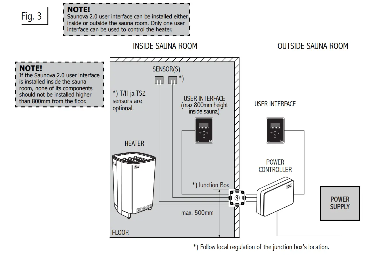
Saunova 2.0 Control Unit is developed to enhance your sauna bathing with a variety of different features. It can adjust temperature, humidity, ventilation and light in your sauna. The Saunova 2.0 Control Units are available on a separate or built-in mounting on the Power Controller.
The following information provides you with instructions on adjusting the settings of the control unit. Please, read this instruction manual carefully before using it. Familiarization of key functions will give you a more enjoyable sauna experience.
 Precautions
|
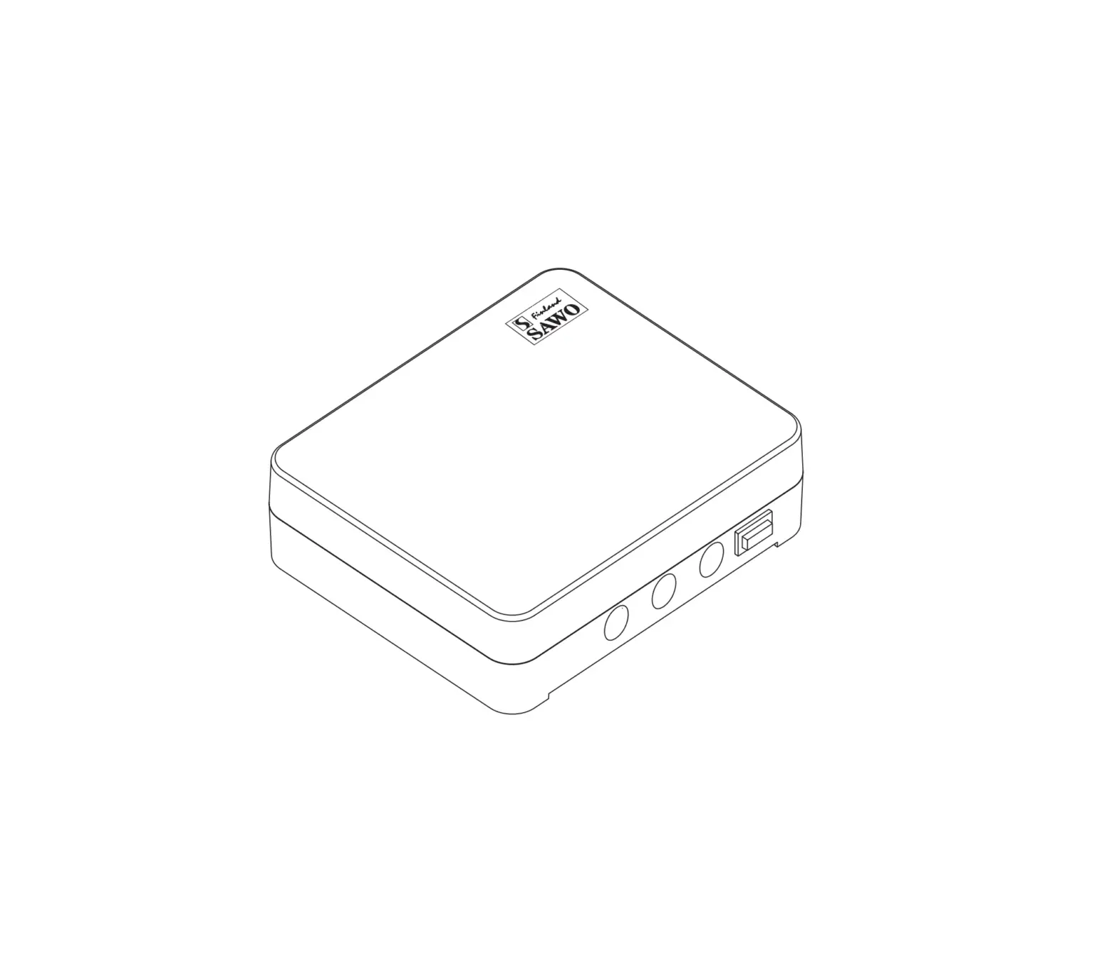
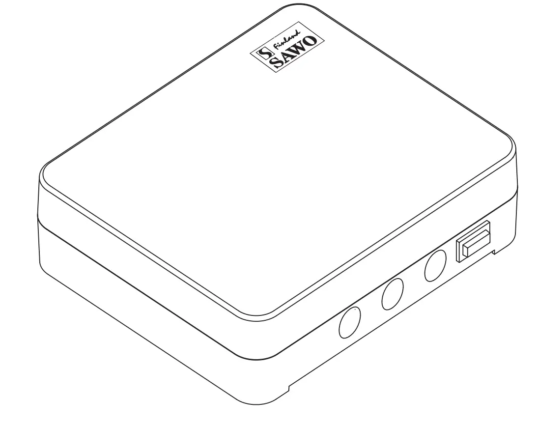
Power Controller
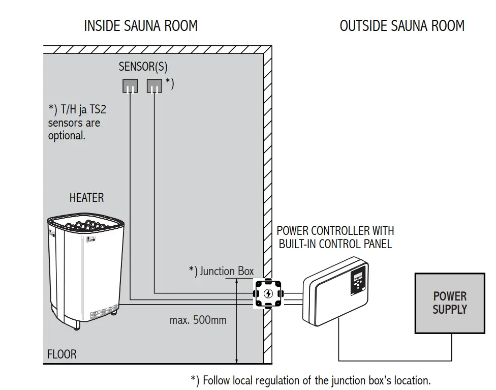
The Power controller or the separate control panel must not be located inside the sauna room or in places where temperature can exceed 40°C. It is protected against water splashes, however it should not get in contact with water. Mount the Power Controller in a dry location, outside the sauna room.
Install the Power Controller on the wall in vertical direction only, at least 30cm from the ceiling (refer to Fig.2).
The heater is connected to the electrical network semi-stationarily with a H07RN-F rubber cable or its equivalent. The use of PVC-insulated cable as a connecting cable is prohibited due to thermal embrittlement. The maximum distance of the junction box from the floor is 500 mm, measured from the upper corner of the box.
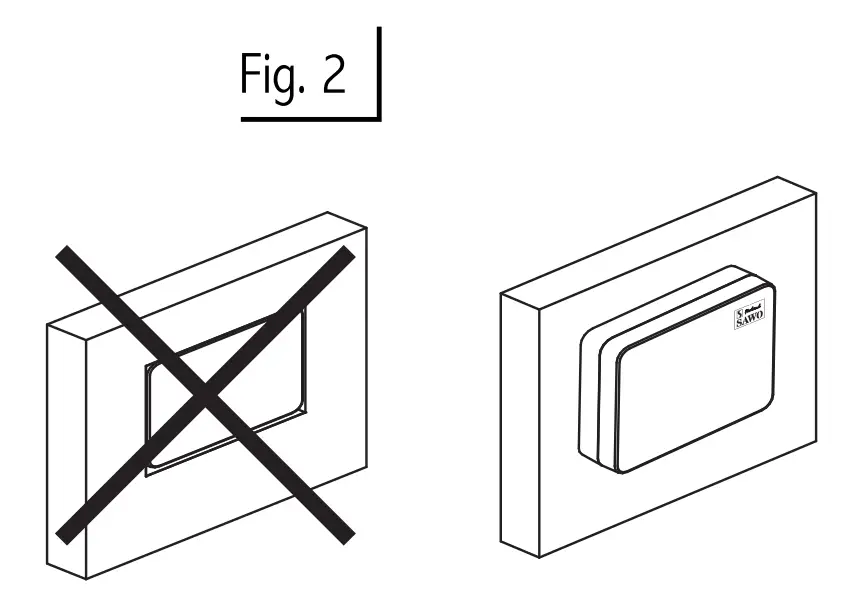
Do not embed the control unit into the wall, because it may lead to overheating of the unit and cause damage! |
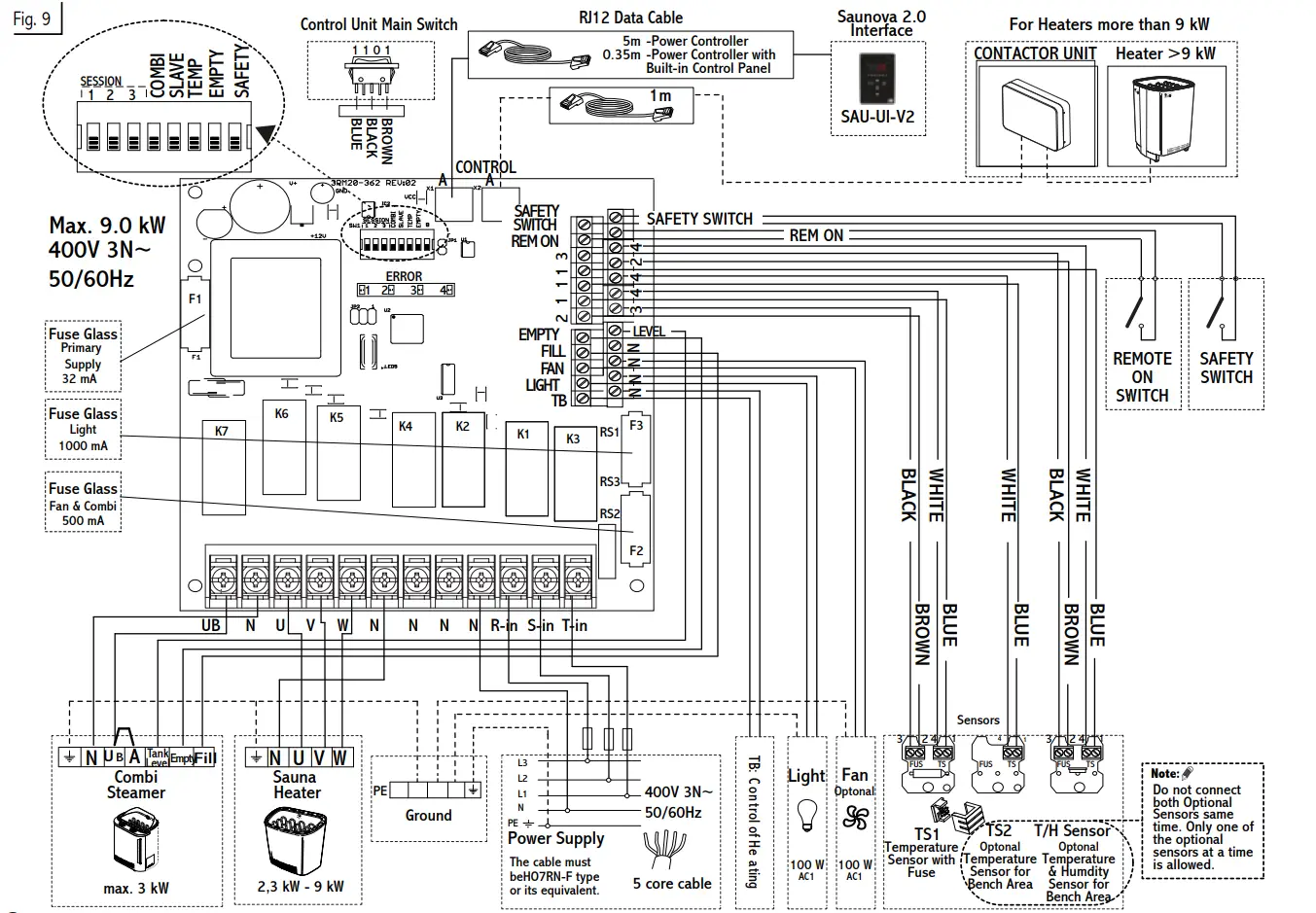
Control Unit to Heater Connection Diagram
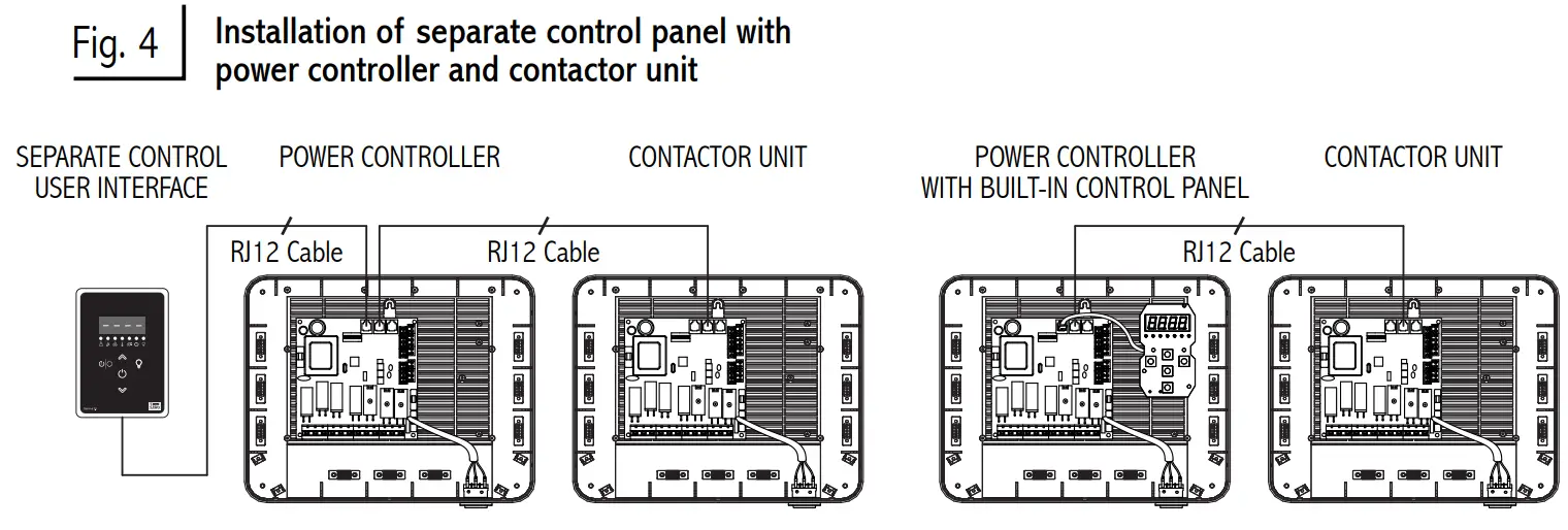
Contactor Unit
If the heater used is more than 9 kW, an additional contactor is needed. The contactor unit is linked to the main Power Controller with a RJ12 cable (Fig.4).
Follow the instructions that are supplied together with the contactor unit.
Sensors
One or two sensors can be connected to the Power Controller. The first sensor measures the temperature, it is the sensor with temperature fuse and thermistor.
The second sensor, the optional bench sensor, is a temperature sensor or combined temperature humidity sensor. The combined sensor is capable of measuring the humidity as well as the temperature.
With two sensors it is possible to receive more accurate measurements from the sauna room.
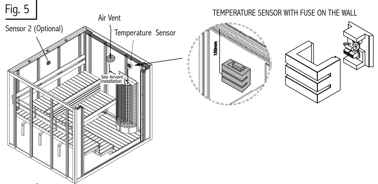
If the heater is mounted on the wall or floor standing less than 200mm from the wall, the first temperature sensor needs to be mounted on the wall above the heater. Place the sensor 150mm from the ceiling (Fig. 5 & 6).
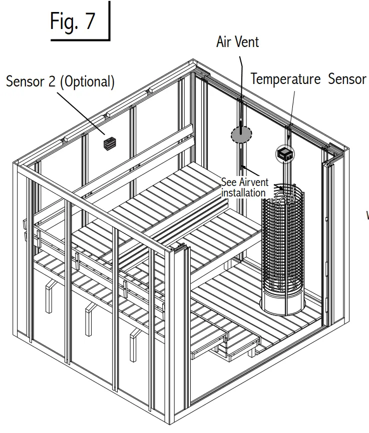
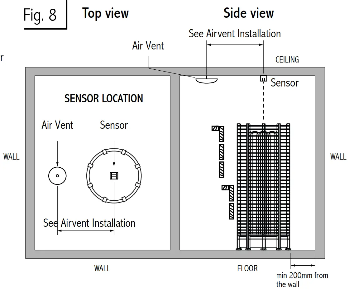
However, if the heater is more than 200mm from the wall, place the sensor to the ceiling, over the heater, as shown in the figure 7 & 8.
The optional second sensor should be mounted on the wall, opposite to the heater, minimum 30cm from the ceiling and minimum 130cm from the floor (fig. 5 & 7 ). It is designed to measure the bench temperature, so ideally place it close to the shoulder height of the sauna goers.
Do not place the sensors near the air ventilation. The closeness of the air vent cools down the sensor. Thus, an incorrect temperature is displayed and the heater may overheat (Fig.8).
Sensor location with heaters mounted on the wall
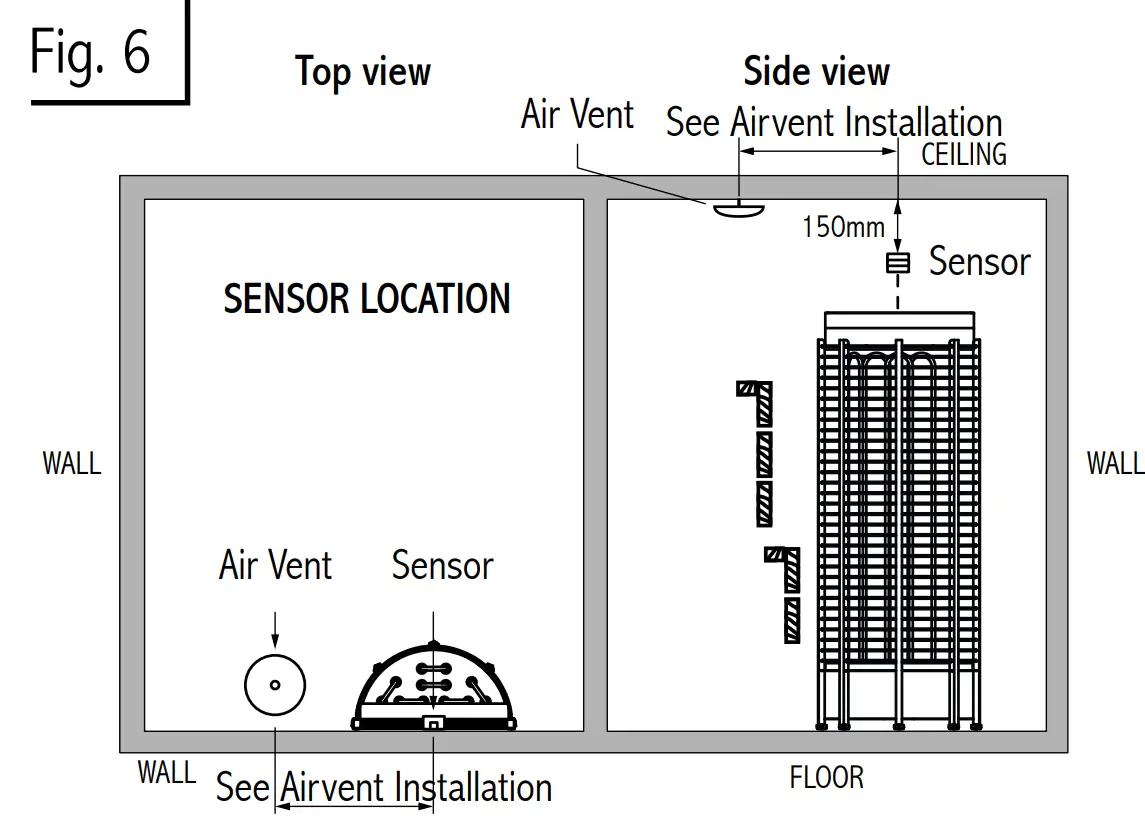
| NOTE Do not place the sensors too near to air ventilation (not under 1000mm) or not under 500mm from air ventilation, which is directed away from sensors. 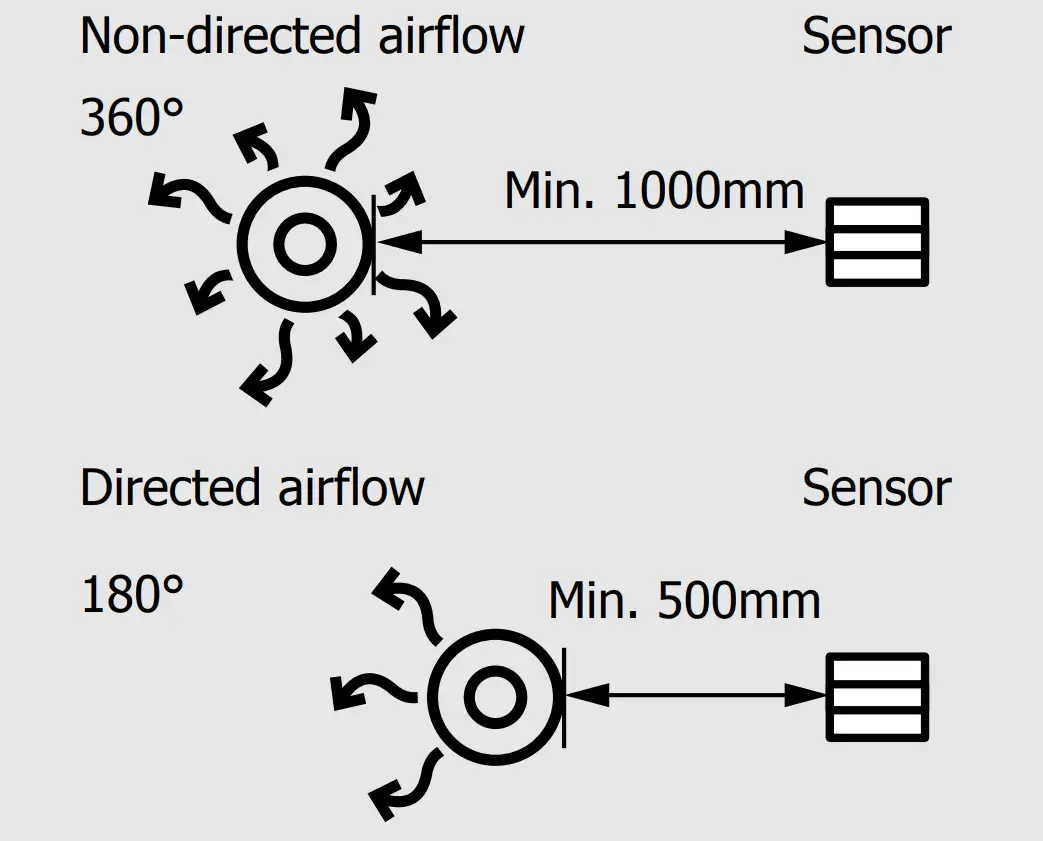 |
Sensor location with heaters mounted on the floor more than 200mm from the wall
Technical Diagram
Maximum Session Time
The maximum sauna session time depends on the purpose of the sauna. For domestic use, the total on-time of the sauna is limited to 6 hours. *)It includes pre-run time and the session time. The factory setting for the control unit is 6 hours
For condominiums, hotels and similar locations, the operating period of the sauna heater is limited to 12 hours, including the pre-run time and the session time.
For public sauna, the operating period of the sauna heater can be either 18 or 24 hours. Please note, if the switches is set to
*) IEC 60335-2-53 Fig. 10
24 hours, it will be ON constantly. It needs to be continuously monitored.
The maximum heater on-time is set by the switches on DIP switch in the power controller, Figure 11 (See also DIP switch session time settings in page 12). Only a qualified electrician can change the settings.
The standards and regulations of the country where the control unit is installed must be followed when setting the DIP switch. Default time is 6 hours. See the Figure 10.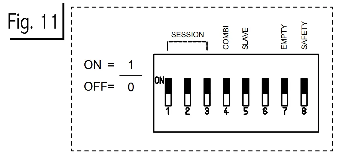
| Sauna Type | Domestic sauna | Hotels, Condominiums | Public sauna | |||||
| DIP switch 1,2,3 | 001 | 010 | 011 | 000 | 100 | 101 | 110 | 111 |
| Max. time | 1h | 2h | 4h | 6h | 8h | 12h | 18h | 24h |
| Sauna on-time | Heater on-time | Session time | ||||||
| Max. pre-run time | 5h 15min- sauna 5h 45min- sauna | 99h | ||||||
Door Sensor/Switch
In other than household use, it is recommended to install door sensor. The door sensor disables all pre-run operations if the door is opened while the pre-run countdown is active
The door sensor also ensures that the door is not open for long periods of time when the heater is on. If the heater is on and the door is open for more than 15minutes, an alarm and “oPEn” will be displayed to warn the user. The heater will be switched off automatically
Fan
The fan function can only be activated if the fan feature is present on the control unit.
Fan can be switched On/Off. The maximum power is 100 W with 230 VAC.
Remote On
Used for automated households. The remote signal is a potential free contact. The sauna heater switches on when contact is closed and remains on until contact is opened.
When the sauna heater is remotely controlled, settings use from previous session are applied. Other buttons are locked. Only the light, Fan and Steamer buttons can be set.
The Power Controller Main Switch
The power controller switch can be found on the top end of the unit. Using this switch, you can isolate the electronics from the mains power supply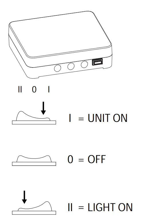
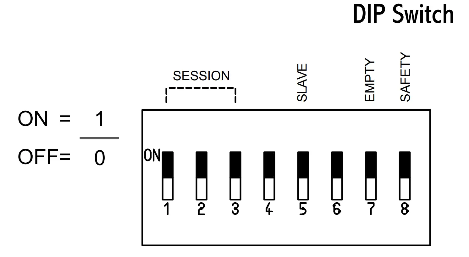
DIP Switch Functions
| DIP Switch # | Function | ON | OFF |
| 1 | Session time | ||
| 2 | Session time | ||
| 3 | Session time | ||
| 4 | Combi mode | Combi mode ON | Combi mode OFF |
| 5 | Slave | Contactor | Controller |
| 6 | – | – | – |
| 7 | Empty | Combi heater with 1 signal (Wm) for water level detection | Combi heater with 2 signal (Empty & Level) for water level detection |
| 8 | Safety/door switch | *Safety switch | **Door sensor/switch |
In DIP switch #8, the Safety Switch function is available when it is switched ON and Door Switch function when it is OFF.
Both functions cannot work at the same time
*Safety Switch
The safety switch function is for a triggering device that will cut the heater connection when a combustible foreign object is thrown to the heater.
When Safety switch is open, the Safety switch is considered to be close, and when Safety switch is closed, the Safety switch is considered to be open.
**Door Sensor/Switch
Install a door sensor and connect it to the control. A signal is channel to the control when the door is open. The control will switch OFF when the door is open during PRE-RUN. When the control is in ON MODE and the door was left open for more than 15mins, the control will switch OFF and turn ON again when the door is close.
When door sensor/switch is open the door is considered to be close, and when door sensor/switch is closed the door is considered to be open.
Session Time
Session time can be set according to user preference by session dip switches on the power controller board.
| Session Time | Switch 1 | Switch 2 | Switch 3 |
| 1h | 0 | 0 | 1 |
| 2h | 0 | 1 | 0 |
| 4h | 0 | 1 | 1 |
| 6h | 0 | 0 | 0 |
| 8h | 1 | 0 | 0 |
| 12h | 1 | 0 | 1 |
| 18h | 1 | 1 | 0 |
| 24h | 1 | 1 | 1 |
| Description | Power Rating | Remarks |
| Control | ||
| Rated Power 3 Phases | 9kW AC1 (3 x 3kW) | |
| Rated Voltage 3 Phases | 400V 3N~ | |
| Rated Power Single Phase | 9kW AC1 | |
| Rated Voltage Single Phase | 230V 1N~ | |
| Frequency | 50/60Hz | |
| Switching capacity per phase | 16A | |
| Sauna temperature range | 10-110°C | |
| Maximum session time (preset) | 1, 2, 4, 6, 8, 12, 18,24h | Restrictions apply according to IEC/EN 60335-2-53 |
| DimensionsSAUNOVA 2.0 Stypes | ||
| User Interface | (W) 104 x (H) 147 x (D) 37 | |
| Power Controller | (W) 270 x (H) 320 x (D) 90 | |
| Weight SAUNOVA 2.0 Stypes | ||
| User Interface | 350g | |
| Power Controller | 2300g | |
| Weight SAUNOVA 2.0 Btypes | 2500g | |
| Steamer | ||
| Rated Power 3 Phases | 3kW AC1 | |
| Rated Power Single Phase | 3kW AC1 | |
| Rated Voltage | 230V 1N~ | |
| Switching capacity | 16A (3 Phases), 16A (1 Phase) | |
| Maximum sauna temperature for steamer operation | 80°Cor *55°C * Depending on the type of Sensor 2. | |
| Automatic water filling | Optional | |
| Cabin Light | Min 20W,max 100W. | |
| Rating | 230V 1N~, 100W AC1 | |
| Fan | Fan without starting capacitor. | |
| Rating | 230V 1N~,0.5A |
| Fuse | |
| Fuse F1 | (32m A) is fuse for electronics |
| Fuse F2 | (1A slow) is fuse for cabin light |
| Fuse F3 | (500m A slow) is fuse for fan and automatic refilling combi. |
| Description | Remarks |
| Sensor | |
| Temperature Sensor with fuse | |
| Bench Sensors | |
| Bench Temperature Sensor | Optional |
| Bench Combined Temperature – Humidity Sensor | Optional |
| Description | Power Rating | Remarks |
| Contactor Unit | ||
| Rated Power 3 Phases | 9kW AC1 (3 x | Additional Power expansion to maximum of 18kW |
| 3kW) | ||
| Rated Voltage 3 Phases | 400V 3N~ | |
| Frequency | 50/60Hz | |
| Switching capacity per phase | 16A |
Subject to change without notice.
www.sawo.com | [email protected]


 Power Control User Manual")


