Aristel AN1808-12S 4G Audio Keypad Intercom Instruction Manual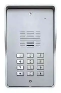
ARISTEL NETWORKS
Thank you for purchasing AN1808-12S SINGLE 4G audio keypad intercom. Please read this manual carefully before using.
Be sure to keep this manual for future reference in case of any problem or question should arise.
Important Safety Instructions
- When using this AN1808-12S SINGLE 4G audio keypad intercom, basic safety precautions should always be followed to reduce the risk of fire, electric shock and personal injury. Please read the following before using your equipment.
- Follow all warning and instructions on the product.
- Unplug all the connections of product before cleaning. Do not use liquid cleaners or aerosol cleaners. Use a damp cloth for cleaning.
- Do not use this product near water.
- Do not use this product near an area where there is a potential of gas leaks or near any fumes that can be explosive.
Do not place this equipment near or over a radiator or any other heat source. - Do not overload the wall outlet or power cord where the power adapter is installed. This can result in fire or electric shock
- Avoid spilling liquid on this equipment and do not insert any objects through the ventilation slots.
- Avoid using the equipment during an electrical storm. There is a remote risk of electrical shock from lighting.
Introduction
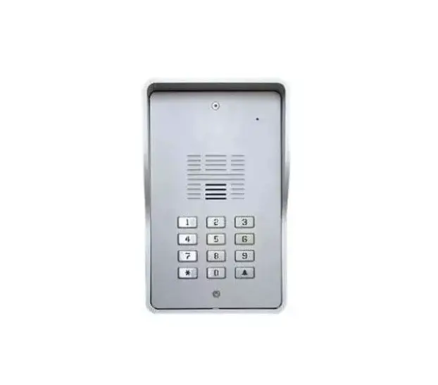
AN1808-12S SINGLE 4G audio keypad intercom system is designed for an apartment, single-family residence and gated communities. It is suitable for a villa or apartment.
When the visitor presses “call button ![]() ” on the intercom it will then call your landline or mobile phone. When answered, you can speak with the visitor and you can open the gate from your phone by entering a password on the dial pad.
” on the intercom it will then call your landline or mobile phone. When answered, you can speak with the visitor and you can open the gate from your phone by entering a password on the dial pad.
The intercom is also an Access Control System to enable users to open the gate with their phone number identity. You need to program the phone numbers of all authorized guests into the dial-to-open numbers of the device before using. When the authorized guest calls the SIM card number in the device, it will check if the calling number is matched in the dial-to-open numbers, if so, it will open your gate.
The intercom accepts 384 different passwords for unlocking the door or gate. If your mobile phone is unavailable, the intercom can open the door by entering a password.
When installing , remember to use an active SIM card with the pin code lock turned off.
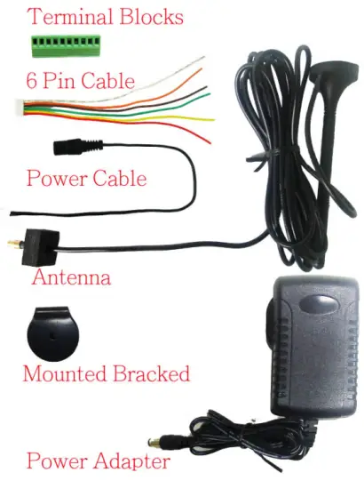
Parts List
| Item | Description | Q’ty |
| 1 | AN1808-12S SINGLE 4G audio intercom | 1 |
| 2 | Power adapter | 1 |
| 3 | External 3-meter antenna | 1 |
| 4 | Mounting Bracket for antenna | 1 |
| 5 | Operating manual | 1 |
| 6 | 6 Pin Cable | 1 |
| 7 | Terminal Blocks | 1 |
Accessories
Installation
This 4G audio intercom is suitable for both flush mounting and surface mounting.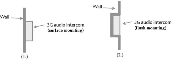
AN1808-12S SINGLE 4G audio Keypad Intercom Unit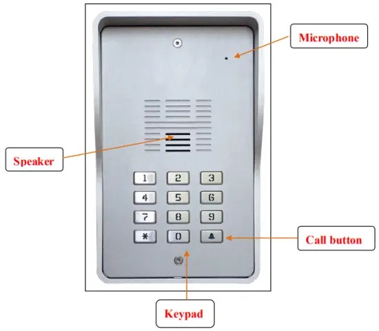
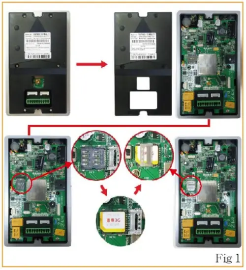
SIM card installation (Fig 1)
- Disconnect the 12V adaptor from the intercom.
- Remove the rear plastic cover
- Remove the SIM card cover from the bottom of the unit
- Slide the SIM card holder towards the front of the unit
- Lift up the holder
- Before inserting the SIM card, ensure that it is not PIN number locked. (If locked, use a mobile phone to unlock it).
- Insert the SIM card (Note orientation of notched corner)
- Replace holder and slide towards the rear of the unit to lock in place
- Replace rear plastic cover

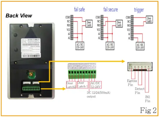
Connecting with the door lock system (Fig 2)
- See below for your relevant door lock type wiring instructions.

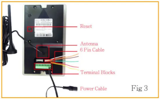
Connecting the Antenna (Fig 3)
- Plug in the antenna cord to the connector on the rear of the unit
- Place the antenna away from electrical/electronic systems (computers, microwave ovens, etc)

Power on.
- Connect the power adaptor into the connector marked AC
- The blue indicator of call button should be on and you will hear Du Du tone.
- Fix the unit in position before activating.
- When the Du Du tone has disappeared, the device is ready.
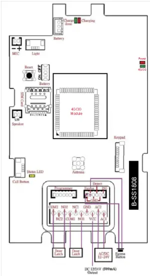
Wiring Diagram
Using the Intercom
- Setting your calling numbers
- Store your phone numbers by SMS.
- The format of text SMS is
*12*1234#11[call out number 1]#12[call out number 2]#13[call out number 3]# - When the setting is finished, the sender will receive the reply as below.
11[call out number 1]#12[call out number 2]#13[call out number 3]#OK - If Visitor presses “call button
 “,
“,
The intercom will call to the three phone numbers in sequence.
- Setting your dial in numbers for authorised guests.
- Send the text SMS to the number of device.
- The format of text SMS is
*12*1234#71[country code]#72[relay][call in number 1]# 72[relay][call in number 2]#… - When the setting is finished, the sender will receive the reply as below.
71[country code]#72[relay][call in number 1]# 72[relay][call in number 2]#…OK - If you call to the number of device through the dial in numbers, the device will
trigger the relay to operate the door latch. - If the number is not matched with the dial in numbers (not authorised guest ) , the device will answer and sound a beep. Then you can enter the programming mode by password as administrator.
- Setting your PIN numbers
- The format of text SMS is
*12*1234#895[X]#87[relay][pin code 1]# 87[relay][pin code 2]#87[relay][pin code 3]#… - When the setting is finished, the sender will receive the reply as below.
895[X]#87[relay][pin code 1]# 87[relay][pin code 2]#87[relay][pin code 3]#…OK - If you press the correct PIN code then the device will trigger the relay to open.
- The format of text SMS is
- App on iOS and Android
- Please search 3G intercom on Apple store or Google Play
- The App will enable remote and speedy programming.
- You can use the App to unlock the door through call or SMS.
- Please call the number of the 4G intercom device.
- The device will answer and sound one beep to enter system menu.
- Enter the password of the mode you would like to enter.
- Listener monitoring mode: 【*13*1212#】
- Access control mode: 【*33*5678#】
- Program setting mode: 【*12* 1234#】
- Password correct one beep, password error 3 beeps.
- 3 times failure attempt on password, the device will hang up the call.
Enter Listener Monitoring Mode
- You will hear a “Do” tone to enter listener monitoring mode by pressing【*13*1212#】 where 1212 is the monitoring password.
- Then you can hear the live sound of the device’s surrounding environment.
- Under this mode speaker is OFF. ( 35#: To turn on speaker)
- You can still control the relay output under listener monitoring mode but speaker must be ON status.
Enter Access Control Mode
- You will hear a “Do” tone to enter access control mode by pressing【*33*5678#】where 5678 is the access control password.
- The door will be opened after entering the correct password
(To open the door by password, if the number is not stored in the call in numbers)
Enter Program setting Mode
- You will hear a “Do” tone to enter into program setting mode by pressing【*12* 1234#】 where 1234 is the setting password.
- You are now in the “program setting mode”
Note: At the end of each command there can be one of the two indications:
Successful: a long “beep” tone, failed: three short “beep” tone. - To make changes on settings please refer to the command codes in page 12.
- To end program setting mode just hang up.
NOTE:
*To be successful in programming, originate a call from a land line and enter the digits slowly or program by text message.
Programming by text message
Programming by text message is the simplest way to customize the settings of the 4G audio intercom and add or delete telephone numbers. Simply send texts in the format to the telephone number of the SIM within the 4G audio intercom.
Note:
- A Single SMS text messages is limited to 140 characters.
- You can program many different user command codes in one text message with SMS command format. *12*1234 # [command Code1] # [command Code 2] # [command Code3] #…
- Each SMS must start with the pass code *12, default setting password 1234 in the following format *12*1234 # followed immediately by a command.
- To program a call button numbers (DO NOT enter country code), just the complete number as you would dial it in local.
Example:
Store a call button phone number (Max 3 numbers) and delete 2&3 phone numbers.
058 57235 (landline number 1)
086 5682554 (mobile number 2)
086 2235644 (mobile number 3)
SMS format: (store a call button phone numbers)
*12*1234#1105857235#120865682554#130862235644#
SMS format: (delete 2&3 phone numbers from a call button)
*12*1234#12*#13*#
User command code CORRECT
SMS format:
*12*1234#1105857235#120865682554#130862235644#
SMS reply:
1105857235#120865682554#130862235644# OK
User command code ERROR (user command 19 error)
SMS format: *12*1234#1105857235#190865682554#130862235644#
SMS reply: 110587235#190865682554# Error
Command Codes
You can program many different command codes in one text message with SMS command format.
*12*1234 # [command Code 1] # [command Code 2] # [command Code 3] #……..
| No. | Feature | Command | Description | Default | |
| 1. | Change setting Password | 01 [ password ] # | password:4 digit codes | 1234 | |
| 2. | Change access control password | 02 [ password ] # | password:4 digit codes | 5678 | |
| 3. | Change monitoring password | 03 [ password] # | password:4 digit codes | 1212 | |
|
4. |
Store or delete call out phone numbers | 1 [ Y ] [ phone number ] # | Y= phone number 1,2 or 3 Phone number= 3~20 digits (One * can be delay 3 seconds) |
None | |
| 1 [ Y ] * # | Delete phone number1, 2, 3 | ||||
| 5. | Speaker Volume | 3 [ speaker volume] # | speaker volume level= 0 ~ 4 | 3 | |
| 6. | Microphone Volume | 4 [ microphone volume] # | microphone volume level= 0 ~ 4 | 3 | |
| 7. | Relay 1 Trigger Time | 51 [ relay1 time ] # | Relay 1 time= 1~9999 sec | 1 | |
| 8. | Relay 2 Trigger Time | 50 [ relay 2 time ] # | Relay 2 time= 1~9999 sec | 1 | |
| 9. | Call Divert to next number time | 52 [ call divert time ] # | Call divert time= 10~99 sec | 20 sec | |
| 10. | Max Call Time | 53 [ max call time] # | Max call time= 005~999 sec | 060 sec | |
| 11. | Max Monitoring time | 55[ duration time] # | duration time= 00 ~ 60 mins 00 ( no limit time) | 10 mins | |
|
12. |
Call in mode |
65[mode] | mode = 1 Setting mode mode = 2 Call mode mode = 3 Reject mode (caller ID permit) |
1 | |
|
13. |
Authorised guests. Call in to open the door numbers (Max: 1150 numbers) | 71 [ country code ] # | Country code= 1~3 digit codes |
None | |
| 72[relay] [ phone number ] # | Relay= 1 or 2 | ||||
| 73 [phone number ] # | Delete phone number | ||||
| 73*# | Delete all phone numbers | ||||
| 14. | Add administrator phone number | 74 [ admin number ] # | admin number= 3~15 digits ( no number no restriction) | None | |
| 15. | Del administrator phone number | 74*# | delete admin phone number | None | |
| 16. | SMS reply notice of Relay status | 894+X# | X=0 (disable SMS reply) X=1 (enable SMS reply) | 0 | |
| 17. | Dial tone volume | 898+X# | X=1~3 (levels) | 2 | |
| 18. | Set Egress Pin output relay | 900[X]# | X=0 (relay 1) X=1 (relay 2) | 0 | |
| 19. | Set Detect pin output relay (Detect Pin is egress mode) | 901[X]# | X=0 (relay 1) X=1 (relay 2) | 1 | |
|
20. |
Detect pin on PCB setup |
902[ X]# | X=0~3 0. disable 1. egress mode (901) 2.trigger 3.resistance=10KΩ(7.5K~13K) |
0 | |
| 21. | Emitting bleep when correct PIN code entered | 903+X# | X=0 (disable) X=1 (enable) | 1 | |
| 22. | Intercom moving Detection (Theft Proof) | 904[X]# | X=0 (disable) X=1 (enable) | 0 | |
| 23. | Set Alert phone number (moving & trigger) | 905[ Y ][ phone number ] # | Y= phone number 1,2 or 3 Phone number=3~15 digits | None | |
| 24. | Enable or disable IN1 | 907[X]# | X=0 (disable) X=1 (enable) | 0 | |
| 25. | Change the length of open code | 940[X]# | X=1 (1 code open code) X=2 (2 codes open code) | 1 | |
|
26. |
Change open codes of relay 1&2 including trigger / hold / release for independent apartment |
93[ABCDEF]# | X= apartment number A,B,C,D,E,F= 0~9 and * A= trigger relay 1 B= hold relay 1 C= release relay 1 D= trigger relay 2 E= hold relay 2 F= release relay 2 | 1 code | 2 code |
| 1 2 3 4 5 6 | 10 20 30 40 50 60 | ||||
| 27. | Send SMS message (when Detect Pin is triggered) | *26*[ password ] #[content] | Password=setting password content= up to 100 characters | Detect PIN Trigger | |
| 28. | Send SMS message (when Intercom is moved) | *27*[ password ]#[content] | Password=setting password content= up to 100 characters | Case open | |
| 29. | Send SMS message (when external power is off) | *28*[ password ]#[content] | Password=setting password content= up to 100 characters | Power loss | |
| (works for inside battery) | |||||
| 30. | Send SMS message (when external power is active) (works for inside battery) | *29*[ password ]#[content] | Password=setting password content= up to 100 characters | Power active | |
| 31. | Send SMS message (when IN1 is triggered) | *30*[ password ]#[content] | Password=setting password content= up to 100 characters | IN1 trigger | |
| 32. | Reset | 999# | reset default | None | |
Keypad command codes
| No. | Feature | Command | Description | Default |
| 1 | Set PIN length for auto enter | 899+X# | X=1~14 | 5 |
| 2 | Set PIN code Type | 895+X# | X=0, only digits X=1, apartment no. with digits | 0 |
| 3 | Store PIN code (Max: 384 sets) | 87+ [relay][PIN code]# | relay=1: relay1 trigger relay=2: relay1 hold/ release relay=3: relay2 trigger relay=4: relay2 hold/ release pin code= 1~14 digits | Empty |
| 4 | Delete PIN code | 88+[relay][PIN code]# | Relay=1~4 | |
| 5 | Delete all PIN code | 88*# | ||
| 6 | PIN code failed attempt times | 890+X# | X=0~9 (times) X= 0 (failed attempt no limit) | 5 |
| 7 | Pause Time after 5 unsuccessful attempts to enter PIN code | 892+X#,1~99分 | X=1~ 99 (minutes) | 1 |
| 8 | Set PIN code error alarm buzzer | 893+X# | X= 0, disable (keypad flashing) X= 1, enable alarm buzzer | 1 |
| 9 | Set keypad LED indicator | 897+X# | X=0 (LED ON) X=1 (LED OFF) | 0 |
How to reset the hardware if you forget your password
- Keep both reset and egress buttons pressed
- Release all buttons after you hearing continuous “Dou” tones
- The device will restart and hardware reset is done
Troubleshooting (Q &A)
Q. The unit keeps bleeping.
A. This means the unit is not able to detect the network for some reason.
- Check the SIM card is activated and has calling credit.
- Power off the unit, remove the SIM and check it in a mobile phone to verify it can make a call.
- Check if the PIN code of SIM disable when put in a phone.
- Check the reception is good. Poor reception is not sufficient.
- Check the antenna has been mounted as high as possible, not near large metal objects, or wet green shrubs etc.
Q. The unit calls the first number, but there is not enough time to answer before it diverts to the next number.
A. Increase the no answer time as per programming instructions.
Q. The unit calls the first number but voicemail comes on before it can ring the second number.
A. Decrease the intercom no answer time as per programming instructions, or extend the ring time on the called phone, before voice mail activates.
Q. The caller ID part does not work.
A. Be sure to program the caller ID part under 72 feature. If your number is a private or number
withheld, then it will not work.
Even if you have already programmed a number to receive a call from the intercom, if you also want that number to have caller ID access, it must be programmed under the 72 feature also. Ensure the number is entered as you would normally dial it from another phone.
Q. There is no audio from the gate, but the person at the gate can hear ok.
A. This can be due to low reception.
- Check reception level by *20#.
- Change SIM card to another network which may have better coverage.
- Purchase a high gain antenna.
Q. The audio quality that can be heard on the remote telephone is poor or humming (buzzing).
A. A small amount of GSM buzz can be considered normal on 4G audio intercoms, but not so much that causes inability to hear the person speaking. This can be caused by the GSM antenna being mounted too close to the speech panel or not mounted high enough.
- Try earthling the speech panel chassis to 0V of the power supply.
- This is also a symptom of poor reception. Try above steps on checking and improving reception.
Q. The key 1 or key 2 does not work when the intercom calls a phone.
A. Check if you can hear the relay clicking at the gate when the key 1 or key 2 is pressed during a
call. If it can be heard, then the system is working, check wiring between the relay and the lock or gate panel. If the relays do not make a clicking sound, then check this feature on a different mobile cell phone or landline. If it works on a different phone, check the settings on the phone in question under DTMF tones. Failure of DTMF tones to operate correctly is also a symptom of low reception.
Check steps above on improving reception. Try pressing the buttons longer when attempting to activate the gates or door.
Specification
| Model | AN1808-12S SINGLE 4G audio Keypad Intercom |
|
GSM / WCDMA Frequency | GSM 850/900/1800/1900 MHz, WCDMA 800/850/900/1900/2100 MHz LTE FDD: B1/B2/B3/B4/B5/B7/B8/B28 LTE TDD: B40 |
| Face plate | 180 (H) x 109 (W) mm |
| Surface back box | 189 (H) x 118 (W) x 65(D) mm |
| Length of antenna | 3 meters cable |
| Power supply | 12~24V AC/ DC |
| Design and material | Vandal resistant / die cast aluminum |
| Humidity | Less than 80% RH |
| Operating Temperature | -20℃ to 50℃ |
| Operating Current | Maximum 250 mA, Typically 55mA |