


Quickstart
This is a
secure
Multilevel Switch
for
.
To run this device please connect it to your mains power supply.
Important safety information
Please read this manual carefully. Failure to follow the recommendations in this manual may be dangerous or may violate the law.
The manufacturer, importer, distributor and seller shall not be liable for any loss or damage resulting from failure to comply with the instructions in this manual or any other material.
Use this equipment only for its intended purpose. Follow the disposal instructions.
Do not dispose of electronic equipment or batteries in a fire or near open heat sources.
What is Z-Wave?
Z-Wave is the international wireless protocol for communication in the Smart Home. This
device is suited for use in the region mentioned in the Quickstart section.

Z-Wave ensures a reliable communication by reconfirming every message (two-way
communication) and every mains powered node can act as a repeater for other nodes
(meshed network) in case the receiver is not in direct wireless range of the
transmitter.
This device and every other certified Z-Wave device can be used together with any other
certified Z-Wave device regardless of brand and origin as long as both are suited for the
same frequency range.
If a device supports secure communication it will communicate with other devices
secure as long as this device provides the same or a higher level of security.
Otherwise it will automatically turn into a lower level of security to maintain
backward compatibility.
For more information about Z-Wave technology, devices, white papers etc. please refer
to www.z-wave.info.
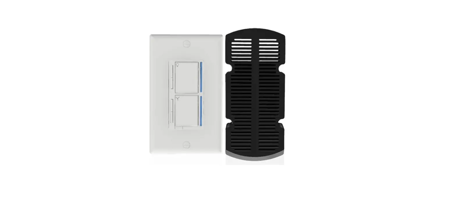
Product Description
The Inovelli Red Series Fan/Light Switch is a 700 Series Z-Wave in-wall fan + light switch that controls both your fan motor and its attached LED, CFL, & Incandescent bulbs which can be highly customized to your liking at the switch itself with our unique config buttons and advanced firmware. In addition, the Red Series comes with advanced features such as scene support, power monitoring, notifications, local protection, etc. This is the first of its kind that allows homes that only have one wire coming from the fan to the light switch and uses both a light switch and canopy module. Inspired and worked on by our wonderful community.
Prepare for Installation / Reset
Please read the user manual before installing the product.
In order to include (add) a Z-Wave device to a network it must be in factory default
state. Please make sure to reset the device into factory default. You can do this by
performing an Exclusion operation as described below in the manual. Every Z-Wave
controller is able to perform this operation however it is recommended to use the primary
controller of the previous network to make sure the very device is excluded properly
from this network.
Safety Warning for Mains Powered Devices
ATTENTION: only authorized technicians under consideration of the country-specific
installation guidelines/norms may do works with mains power. Prior to the assembly of
the product, the voltage network has to be switched off and ensured against re-switching.
Inclusion/Exclusion
On factory default the device does not belong to any Z-Wave network. The device needs
to be added to an existing wireless network to communicate with the devices of this network.
This process is called Inclusion.
Devices can also be removed from a network. This process is called Exclusion.
Both processes are initiated by the primary controller of the Z-Wave network. This
controller is turned into exclusion respective inclusion mode. Inclusion and Exclusion is
then performed doing a special manual action right on the device.
Quick trouble shooting
Here are a few hints for network installation if things dont work as expected.
- Make sure a device is in factory reset state before including. In doubt exclude before include.
- If inclusion still fails, check if both devices use the same frequency.
- Remove all dead devices from associations. Otherwise you will see severe delays.
- Never use sleeping battery devices without a central controller.
- Dont poll FLIRS devices.
- Make sure to have enough mains powered device to benefit from the meshing
Association – one device controls an other device
Z-Wave devices control other Z-Wave devices. The relationship between one device
controlling another device is called association. In order to control a different
device, the controlling device needs to maintain a list of devices that will receive
controlling commands. These lists are called association groups and they are always
related to certain events (e.g. button pressed, sensor triggers, …). In case
the event happens all devices stored in the respective association group will
receive the same wireless command wireless command, typically a ‘Basic Set’ Command.
Association Groups:
Group NumberMaximum NodesDescription
| 1 | 5 | Lifeline group. Members of this group will receive unsolicited messages related to the status of the switch. |
| 2 | 5 | Sends On & Off commands to associated devices. (1. Single press UP button sends BasicSet (0xFF) and 2. Single press Down sends BasicSet (0x00) |
| 3 | 5 | Sends set level commands to associated devices when switch is pressed.(1. Hold & Release Up or Down button sends SwitchMultiLevelSet which keeps associated devices in sync with this device. 2. Single press Up button sends SwitchMultiLevelSet(0xFF) and 4. Single press Down button sends SwitchMultiLevelSet(0x00) |
| 4 | 5 | Sends start / stop level change to associated devices.(1. Hold Up button sends SW_MULTILEVEL_START_LEVEL_CHANGE (Up)2: Hold Down button sends SW_MULTILEVEL_START_LEVEL_CHANGE (Down) 3. Release Either button sends SW_MULTILEVEL_STOP_LEVEL_CHANGE |
| 5 | 5 | Sends On & Off commands to associated devices. (1. Single press UP button sends BasicSet (0xFF) and 2. Single press Down sends BasicSet (0x00) |
| 6 | 5 | Sends set level commands to associated devices when switch is pressed.(1. Hold & Release Up or Down button sends SwitchMultiLevelSet which keeps associated devices in sync with this device. 2. Single press Up button sends SwitchMultiLevelSet(0xFF) and 4. Single press Down button sends SwitchMultiLevelSet(0x00) |
| 7 | 5 | Sends start / stop level change to associated devices.(1. Hold Up button sends SW_MULTILEVEL_START_LEVEL_CHANGE (Up)2: Hold Down button sends SW_MULTILEVEL_START_LEVEL_CHANGE (Down) 3. Release Either button sends SW_MULTILEVEL_STOP_LEVEL_CHANGE |
Configuration Parameters
Z-Wave products are supposed to work out of the box after inclusion, however
certain configuration can adapt the function better to user needs or unlock further
enhanced features.
IMPORTANT: Controllers may only allow configuring
signed values. In order to set values in the range 128 … 255 the value sent in
the application shall be the desired value minus 256. For example: To set a
parameter to 200 it may be needed to set a value of 200 minus 256 = minus 56.
In case of a two byte value the same logic applies: Values greater than 32768 may
needed to be given as negative values too.
Parameter 1: Dimming Speed – Light
This changes the speed in which the attached light dims up or down. A setting of 0 should turn the light immediately on or off (almost like an on/off switch). Increasing the value should slow down the transition speed.
Size: 1 Byte, Default Value: 3
SettingDescription
| 0 – 100 | Speed at which light dims up or down (increments) |
Parameter 10: Auto Off TimerLight
Automatically turns the light off after this many seconds. When the switch is turned on a timer is started that is the duration of this setting. When the timer expires, the switch is turned off.
Size: 2 Byte, Default Value: 0
SettingDescription
| 0 | Disabled |
| 1 – 32767 | Seconds |
Parameter 11: Auto Off TimerFan
Automatically turns the fan off after this many seconds. When the fan is turned on a timer is started that is the duration of this setting. When the timer expires, the fan is turned off.
Size: 2 Byte, Default Value: 0
SettingDescription
| 0 | Disabled |
| 1 – 32767 | Seconds |
Parameter 12: Default Level (Local)Light
Default level for the dimmer when it is powered on from the local switch. A setting of 0 means that the switch will return to the level that it was on before it was turned off.
Size: 1 Byte, Default Value: 0
SettingDescription
| 0 | Sets back to light level prior to switch turning off |
| 1 – 99 | Sets light to a certain default dim level (ie: 1-99%) when powered on |
Parameter 13: Default Level (Z-Wave)Light
Default level for the dimmer when it is powered on from a Z-Wave command. A setting of 0 means that the switch will return to the level that it was on before it was turned off.
Size: 1 Byte, Default Value: 0
SettingDescription
| 0 | Sets back to light level prior to switch turning off – via Z-Wave Command |
| 1 – 99 | Sets light to a certain default dim level (ie: 1-99%) when powered on – via Z-Wave Command |
Parameter 14: Default Level (Local)Fan
Default level for the fan when it is powered on from the local switch. A setting of 0 means that the switch will return to the level that it was on before it was turned off
Size: 1 Byte, Default Value: 0
SettingDescription
| 0 | Sets back to fan level prior to switch turning off |
| 1 – 99 | Sets fan to a certain default dim level (ie: 1-99%) when powered on |
Parameter 15: Default Level (Z-Wave)Fan
Default level for the fan when it is powered on from a Z-Wave command. A setting of 0 means that the switch will return to the level that it was on before it was turned off.
Size: 1 Byte, Default Value: 0
SettingDescription
| 0 | Sets back to fan level prior to switch turning off – Z-Wave |
| 1 – 99 | Sets fan to a certain default dim level (ie: 1-99%) when powered on – Z-Wave |
Parameter 16: State After Power Restored Light
The state the switch should return to once power is restored after power failure. 0 = off, 1-99 = level, 100=previous
Size: 1 Byte, Default Value: 100
SettingDescription
| 0 | Off |
| 1 – 99 | Turns on to a certain percentage (1-99%) |
| 100 | Returns to previous state the light was in prior to a power outage |
Parameter 17: State After Power Restored Fan
The state the switch should return to once power is restored after power failure. 0 = off, 1-99 = level, 100=previous.
Size: 1 Byte, Default Value: 0
SettingDescription
| 0 | Off |
| 1 – 99 | Turns on to a certain percentage (1-99%) |
| 100 | Returns to previous state the fan was in prior to power outage |
Parameter 18: Default LED Strip ColorLight
This is the color of the Light LED strip represented as part of the HUE color wheel. Since the wheel has 360 values and this parameter only has 255, the following equation can be used to determine the color: value/255 * 350 = Hue color wheel value
Size: 1 Byte, Default Value: 170
SettingDescription
| 0 – 255 | Color values |
Parameter 19: Default LED Strip IntensityLight
This is the intensity of the LED strip.
Size: 1 Byte, Default Value: 5
SettingDescription
| 0 – 9 | Intensity of the LED strip |
Parameter 2: Dimming Speed (From Switch) – Light
This changes the speed in which the attached light dims up or down when controlled from the physical switch. A setting of 0 should turn the light immediately on or off (almost like an on/off switch). Increasing the value should slow down the transition speed. A setting of 99 should keep this in sync with parameter 1.
Size: 1 Byte, Default Value: 99
SettingDescription
| 0 – 98 | Speed at which light dims up and down (from switch) |
| 99 | Sync to Parameter 1 |
Parameter 20: Default LED Strip ColorFan
This is the color of the Fan LED strip represented as part of the HUE color wheel. Since the wheel has 360 values and this parameter only has 255, the following equation can be used to determine the color: value/255 * 350 = Hue color wheel value
Size: 1 Byte, Default Value: 170
SettingDescription
| 0 – 255 | Color values |
Parameter 21: Default LED Strip Intensity Fan
This is the intensity of the fan LED strip.
Size: 1 Byte, Default Value: 5
SettingDescription
| 0 – 9 | Intensity of the Fan LED strip |
Parameter 22: Default LED Strip Intensity (When OFF)Light
This is the intensity of the Light LED strip when the switch is off. This is useful for users to see the light switch location when the lights are off.
Size: 1 Byte, Default Value: 1
SettingDescription
| 0 – 9 | Intensity of the Light LED strip (when lights are off) |
Parameter 23: Default LED Strip Intensity (When OFF)Fan
This is the intensity of the Fan LED strip when the switch is off. This is useful for users to see the light switch location when the lights are off.
Size: 1 Byte, Default Value: 1
SettingDescription
| 0 – 9 | Intensity of the Fan LED strip (when fan is off) |
Parameter 24: LED Strip EffectLight
This will allow you to add some sweet effects to your LED Bar (i.e.: pulse, chase, solid, etc). Byte 1 = Color, Byte 2 = Brightness Level, Byte 3 = Effect, Byte 4 = Duration. *Please see website for further instructions on how to set this up
Size: 4 Byte, Default Value: 0
SettingDescription
| 0 – 4294967295 | Please see website instructions to set this up: https://nathanfiscus.github.io/inovelli-notification-calc/ |
Parameter 25: LED Strip EffectFan
This will allow you to add some sweet effects to your LED Bar (i.e.: pulse, chase, solid, etc). Byte 1 = Color, Byte 2 = Brightness Level, Byte 3 = Effect, Byte 4 = Duration. *Please see website for further instructions on how to set this up
Size: 4 Byte, Default Value: 0
SettingDescription
| 0 – 4294967295 | Please see website instructions to set this up: https://nathanfiscus.github.io/inovelli-notification-calc/ |
Parameter 26: Timeout for LED BarLight
When the LED strip is disabled (Light LED Strip Intensity is set to 0), this setting allows the LED strip to turn on temporarily while being adjusted.
Size: 1 Byte, Default Value: 3
SettingDescription
| 0 | Disabled |
| 1 – 10 | Intensity level |
Parameter 27: Name: Timeout for LED BarFan
When the LED strip is disabled (Fan LED Strip Intensity is set to 0), this setting allows the LED strip to turn on temporarily while being adjusted.
Size: 1 Byte, Default Value: 3
SettingDescription
| 0 | Disabled |
| 1 – 10 | Intensity Level |
Parameter 28: Active Power Reports
The power level change that will result in a new power report being sent. The value is a percentage of the previous report. 0 = disabled.
Size: 1 Byte, Default Value: 10
SettingDescription
| 0 | Disabled |
| 1 – 100 | Percentage of the previous report |
Parameter 29: Periodic Power & Energy Reports
Time period between consecutive power & energy reports being sent (in seconds). The timer is reset after each report is sent
Size: 2 Byte, Default Value: 3600
SettingDescription
| 0 | Disabled |
| 1 – 32767 | Seconds |
Parameter 3: Ramp Rate
This changes the speed in which the attached light turns on or off. For example, when a user sends the switch a basicSet(value: 0xFF) or basicSet(value: 0x00), this is the speed in which those actions take place. A setting of 0 should turn the light immediately on or off (almost like an on/off switch). Increasing the value should slow down the transition speed. A setting of 99 should keep this in sync with parameter 1.
Size: 1 Byte, Default Value: 99
SettingDescription
| 1 – 98 | Speed at which the light turns on and off |
| 99 | Sync to Parameter 1 |
Parameter 30: Energy Reports
Energy level change which will result in sending a new energy report. Available settings: 1-127 (0.01-1.27 kWh) 0 = disabled.
Size: 1 Byte, Default Value: 10
SettingDescription
| 0 | Disabled |
| 1 – 100 | Percentage of the previous report |
Parameter 4: Ramp Rate (From Switch)
This changes the speed in which the attached light turns on or off from the physical switch. For example, when a user presses the up or down button, this is the speed in which those actions take place. A setting of 0 should turn the light immediately on or off (almost like an on/off switch). Increasing the value should slow down the transition speed. A setting of 99 should keep this in sync with parameter 1.
Size: 1 Byte, Default Value: 99
SettingDescription
| 0 – 98 | Speed at which the light turns on and off (from switch) |
| 99 | Sync to Parameter 1 |
Parameter 5: Minimum LevelLight
The minimum level that the dimmer allows the bulb to be dimmed to. Useful when the user has a bulb that does not turn on at a lower level.
Size: 1 Byte, Default Value: 1
SettingDescription
| 1 – 45 | Minimum % level the bulb can be dimmed down to |
Parameter 6: Maximum LevelLight
The maximum level that the dimmer allows the bulb to be dimmed to. Useful when the user has an LED bulb that reaches its maximum level before the dimmer value of 99.
Size: 1 Byte, Default Value: 99
SettingDescription
| 55 – 99 | Maximum % level the bulb can be dimmed up to |
Parameter 7: Minimum LevelFan
The minimum level that the dimmer allows the fan to be dimmed to. Useful when the user has a fan that does not turn on at a lower level.
Size: 1 Byte, Default Value: 1
SettingDescription
| 1 – 45 | Minimum % level the fan can be dimmed down to |
Parameter 8: Name: Maximum LevelFan
The maximum level that the dimmer allows the fan to be dimmed to.
Size: 1 Byte, Default Value: 99
SettingDescription
| 55 – 99 | Maximum % level the fan can be dimmed up to |
Parameter 9: Invert Switch
Inverts the switch (Tap Down = On, Tap Up = Off). 0 = Disabled, 1 = Enabled
Size: 1 Byte, Default Value: 0
SettingDescription
| 0 | Disabled |
| 1 | Enabled |
Technical Data
| Hardware Platform | ZGM130 |
| Device Type | Multilevel Switch |
| Network Operation | Always On Slave |
| Firmware Version | HW: 1 FW: 1.27 |
| Z-Wave Version | 7.13.4 |
| Certification ID | ZC12-20060074 |
| Z-Wave Product Id | 0x031E.0x000E.0x0001 |
| Electric Load Type | Dimmable LEDInductive (e.g. Motor) |
| Neutral Wire Required | ok |
| Color | White |
| Switch Type | Decorator Paddle Push |
| Z-Wave Scene Type | Central Scene |
| Firmware Updatable | Updatable by Manufacturer |
| Security V2 | S2_UNAUTHENTICATED ,S2_AUTHENTICATED |
| Frequency | XXfrequency |
| Maximum transmission power | XXantenna |
Supported Command Classes
- Application Status
- Association Grp Info V3
- Association V2
- Basic V2
- Central Scene V3
- Configuration V4
- Device Reset Locally
- Firmware Update Md V5
- Indicator V3
- Manufacturer Specific V2
- Meter V3
- Multi Channel Association V3
- Multi Channel V4
- Powerlevel
- Protection V2
- Security
- Security 2
- Supervision
- Switch Multilevel V4
- Transport Service V2
- Version V3
- Zwaveplus Info V2
Controlled Command Classes
- Basic V2
- Switch Multilevel V4
Explanation of Z-Wave specific terms
- Controller — is a Z-Wave device with capabilities to manage the network.
Controllers are typically Gateways,Remote Controls or battery operated wall controllers. - Slave — is a Z-Wave device without capabilities to manage the network.
Slaves can be sensors, actuators and even remote controls. - Primary Controller — is the central organizer of the network. It must be
a controller. There can be only one primary controller in a Z-Wave network. - Inclusion — is the process of adding new Z-Wave devices into a network.
- Exclusion — is the process of removing Z-Wave devices from the network.
- Association — is a control relationship between a controlling device and
a controlled device. - Wakeup Notification — is a special wireless message issued by a Z-Wave
device to announces that is able to communicate. - Node Information Frame — is a special wireless message issued by a
Z-Wave device to announce its capabilities and functions.


 Lzw30-sn Manual")

