YAMAHA Boundary Microphone RM-TT User Manual
INTRODUCTION
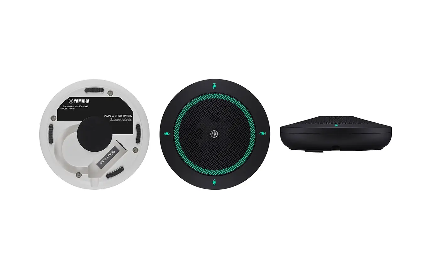
Thank you for purchasing the Yamaha RM-TT boundary microphone. This document provides detailed information on the product functions and specifications as well as the Web GUI. For correct and safe use of this product, be sure to first read this manual carefully together with the RM-TT Installation Manual (included with the product).
Information
- The illustrations and images shown in this manual are for instructional purposes only.
- The company names and product names in this manual are trademarks or registered trademarks of their respective companies.
- We are continuously improving the software for our products. The latest version can be downloaded from the Yamaha website.
- This document is based on the latest specifications at the time of publication. The latest version can be downloaded from the Yamaha website.
- Reproduction of this manual in whole or in part without permission is prohibited.
CONTROLS AND FUNCTIONS
Top panel/side panel
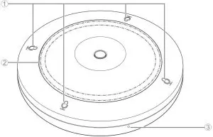
 (Mic) buttons/indicators
Condition
Mic indicator Unit status
Mic button touched
Lit green Microphone on
Mic button touched
Lit red
(Flashes every 2 seconds)Microphone off
- STATUS indicator
Condition
STATUS indicator Unit status
Mic button touched Lit green Microphone on Mic button touched Lit red Microphone off LAN cable plugged into Dante/PoE port Flashes green Starting up Identify button in Web GUI clicked Flashes white Responding (to Identify function) Updating firmware Flashes white quickly Firmware being updated Updating firmware (After flashing white quickly) Flashes green quickly Firmware updated successfully –
Flashes red Error occurring –
Flashes red quickly Severe error occurring - RESET button
Condition
STATUS indicator Unit status
RESET button long-pressed for 4 seconds to less than 8 seconds, then released Flashes blue twice per second (during long-pressing/resetting) Network-related settings Waiting for resetting/Resetting RESET button long-pressed for 8 seconds to less than 12 seconds, then released Flashes blue three times per second (during long-pressing/resetting) All settings
Waiting for resetting/Resetting
NOTE: Use a fine-tipped object such as an ejector pin to press the RESET button.
Bottom panel
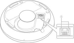
- Network port indicators (Dante/PoE port)
Network port indicator
Unit status Left indicator lit green Link up
Left indicator flashes green
Transferring data Left indicator unlit Link down
Right indicator lit green
Operating on word clock of peripheral device (master) Right indicator flashes green
Acting as word-clock master
Right indicator flashes orange Word clock unlocked
NOTICE:
- When disconnecting the LAN cable from the Dante/PoE port, wait at least five seconds before reconnecting the cable. Otherwise, damage or malfunctions may result.
- With a Dante network, do not use the EEE function* of the network switch. Although mutual power consumption settings are automatically adjusted between switches that support the EEE function, some switches do not perform that properly. As a result, the switch’s EEE function may be enabled inappropriately in the Dante network, possibly degrading clock synchronization performance and interrupting audio. Therefore, please note the following.
- When using managed switches, turn off the EEE function on all ports used for Dante. Do not use a switch that does not allow the EEE function to be turned off.
- When using unmanaged switches, do not use switches that support the EEE function. In such switches, the EEE function cannot be turned off.
- EEE (Energy-Efficient Ethernet) function: Technology that reduces the power consumption of Ethernet devices during periods of low network traffic; also known as Green Ethernet or IEEE802.3az.
WEB GUI
The Web GUI “Peripheral Detail / RM-TT” can be used to check/change the settings of this unit.
IMPORTANT: The setup of the ADECIA tabletop solution must be completed in advance. For details, refer to the RM-CR Reference Manual.
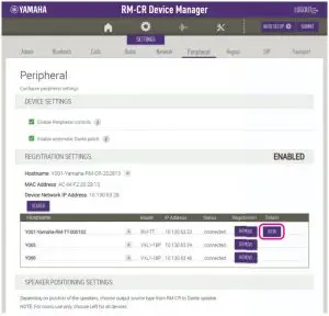
Starting Peripheral Detail / RM-TT
- Log in to the Web GUI “RM-CR Device Manager”.
- Click [SETTINGS], and then click [Peripheral].
- Check that the information for this unit appears in the [REGISTRATION SETTINGS] list, and then click its [VIEW] button below [Details].
Peripheral Detail / RM-TT starts up.
Functions of Peripheral Detail / RM-TT
The following icons/buttons are used in Peripheral Detail / RM-TT.
![]() (Information icon): Move the pointer over this icon to see more information about the item.
(Information icon): Move the pointer over this icon to see more information about the item.
![]() (Identify button): Click to cause the indicator of the corresponding device to flash.
(Identify button): Click to cause the indicator of the corresponding device to flash.
IMPORTANT: Be sure to click the [SUBMIT] button after changing settings in Peripheral Detail / RM-TT. The [SUBMIT] button always appears in the upper-right corner of the window.
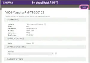
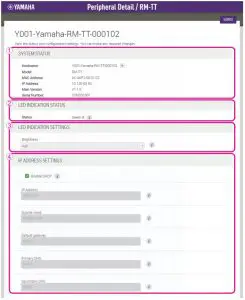
- SYSTEM STATUS
Allows you to check basic information on this unit. - LED INDICATION STATUS
Allows you to check the status of the indicators. - LED INDICATION SETTINGS
Allows you to check/adjust the brightness of the indicators. - IP ADDRESS SETTINGS
Allows you to select whether to use DHCP.
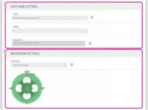
- HOST NAME SETTINGS
Allows you to select whether to specify the hostname of this unit automatically or manually.
- MICROPHONE SETTINGS
Allows you to set the directivity of the microphone to one of the following.- Auto voice tracking
- Cardioid
- Hypercardioid
- Supercardioid
- Omnidirectional
- Bidirectional
- Toroid
NOTE: When the directivity of the microphone is set to cardioid, hypercardioid or supercardioid, you can check/change auto mix settings.
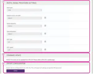
- DIGITAL SIGNAL PROCESSING SETTINGS
Allows you to check/change settings for the following.- Input gain
- Adaptive echo canceller
- Noise reduction
- Dereverberation
- Auto gain control (type and speed)
- FIRMWARE UPDATE
Allows you to update the firmware from the [Update] window of RM-CR Device Manager. For details, refer to the RM-CR Reference Manual. - EXPORT CONFIGURATION
Allows you to export the settings of this unit by clicking the [EXPORT] button.
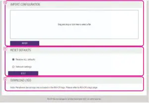
- IMPORT CONFIGURATION
Allows you to import settings into this unit by dragging and dropping the settings file into the box, then clicking the [IMPORT] button.
NOTE: Create the settings file to be imported by editing the one exported in 9. - RESET DEFAULTS
Allows you to reset the settings of this unit by clicking the [RESET] button.
IMPORTANT: Be sure to check what is to be reset before doing it. - DOWNLOAD LOGS
Allows you to update the download log from the [Logs] window of RM-CR Device Manager. For details, refer to the RM-CR Reference Manual.
Manual Development Group
© 2021 Yamaha Corporation
Published 05/2021
IP-A0


![Yamaha Cs-700 Extension Microphone [xm-cs-700] User Manual](https://static-data1.manualsee.com/1/img/165/57374/2021/02/Yamaha-CS-700-Extension-Microphone-XM-CS-700-User-Manual.jpg "Yamaha Cs-700 Extension Microphone [xm-cs-700] User Manual")


