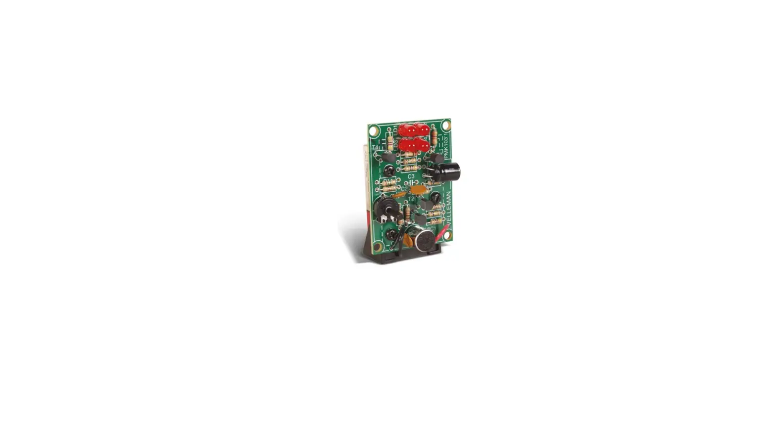
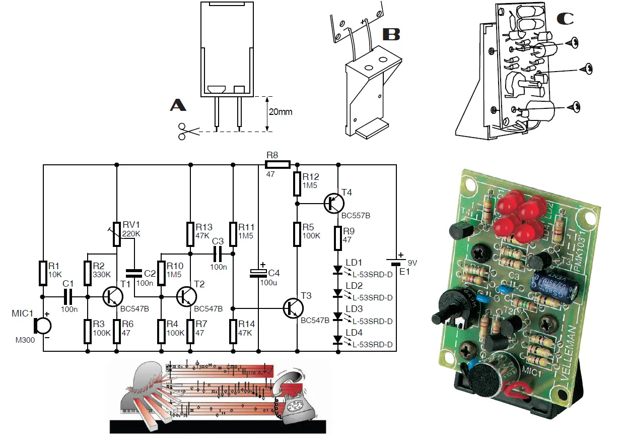
velleman MK103 Sound-To-Light Unit
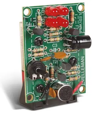
MK103
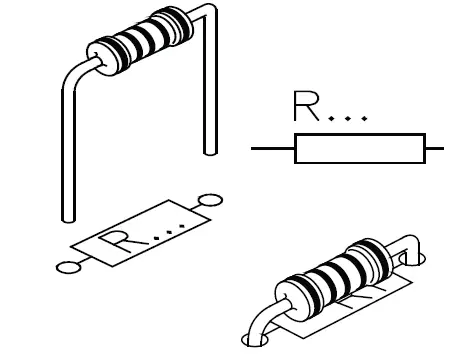
- Resistor
- RR1: 10K
- (Brown, Black, Orange)
- R2: 330K
- (Orange, Orange, Yellow)
- R3 … R5 : 100K
- Brown, Black, Yellow)
- R6 … R9 : 47E
- (Yellow, Purple, Black)
- R10 … R12 : 1M5
- (Brown, Green, Green)
- R13, R14 : 47K
- (Yellow, Purple, Orange)

- (Yellow, Purple, Orange)
- RR1: 10K
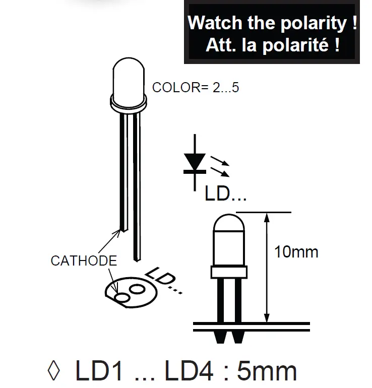
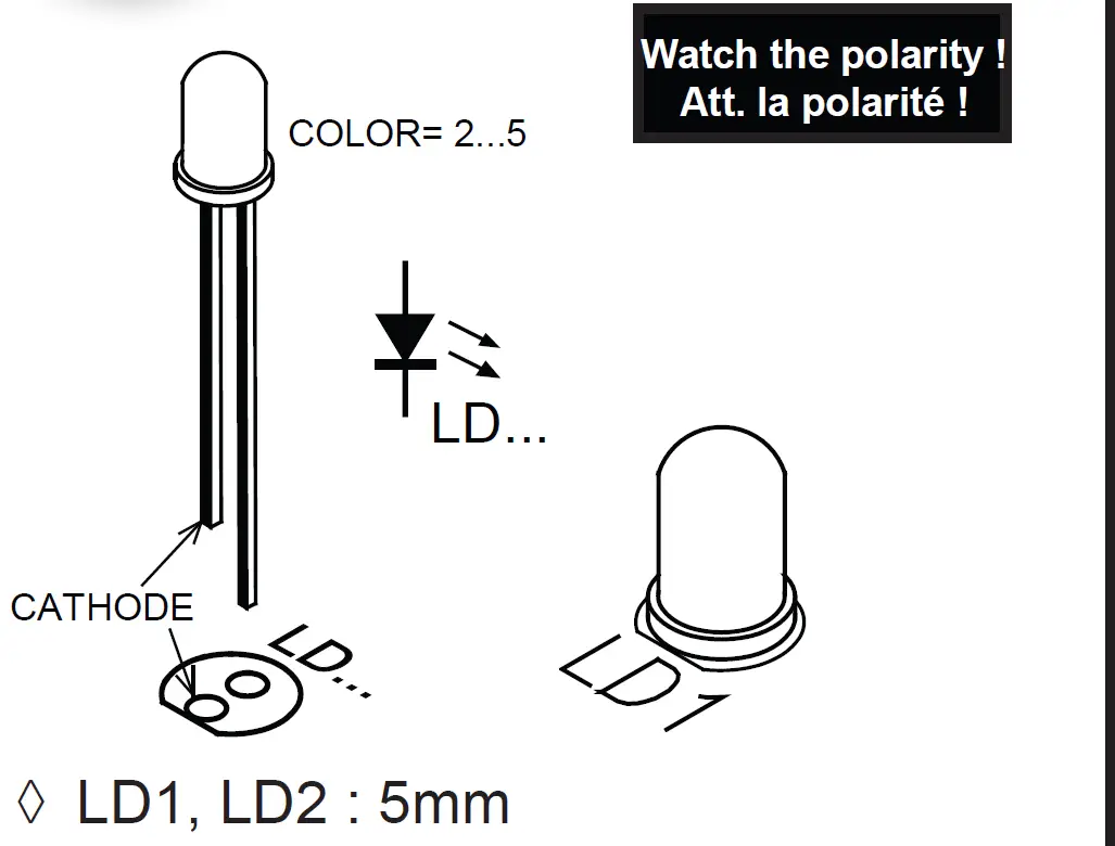
- LED

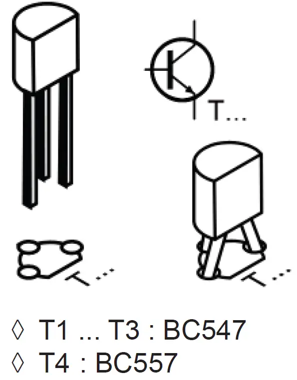
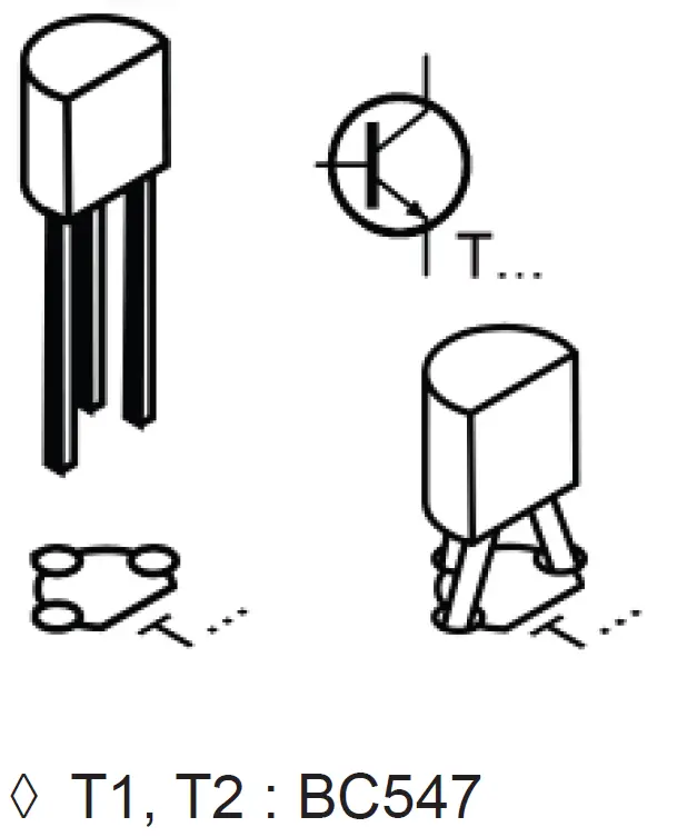
- Transistor

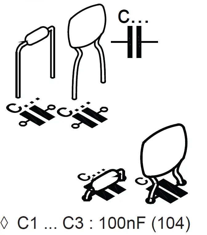
- Ceramic capacitors

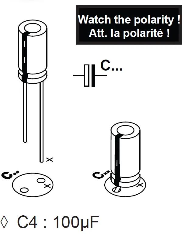
- Electrolytic capacitors

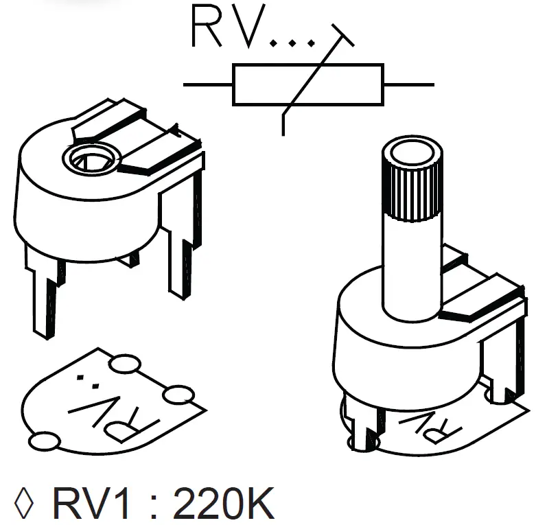
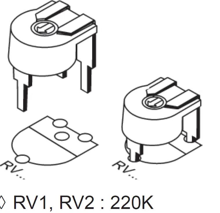
- Horizontal Trimmer

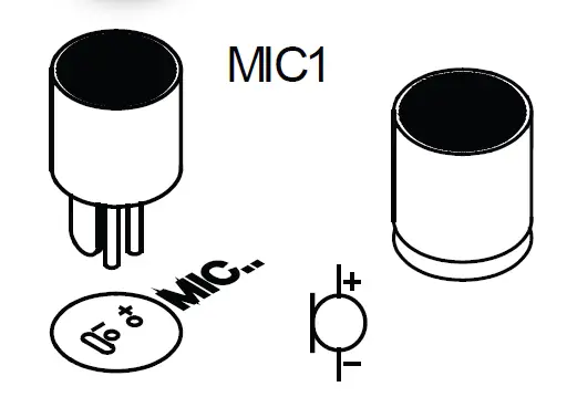
- Microphone


MK102
- Resistor
- R1, R2 : 1K
- (Brown, Black, Red)
- R3, R4 : 10K
- (Brown, Black, Orange
- (Brown, Black, Orange
- R1, R2 : 1K
- Trimmer

- Transistor

- LED

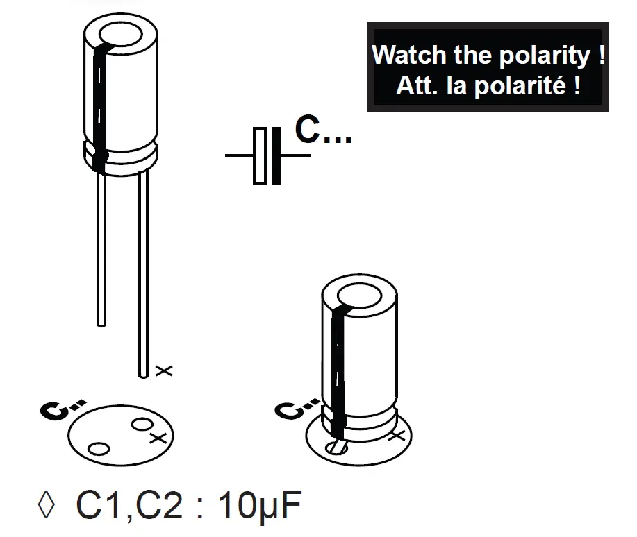
- Electrolytic capacitors

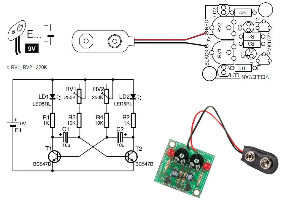
- Battery snap

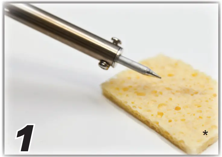
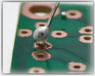
HOW TO SOLDER?
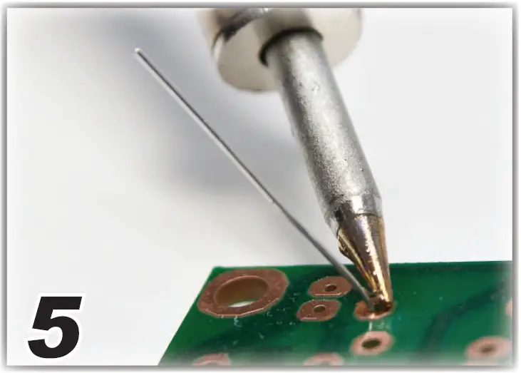
- Wipe tip

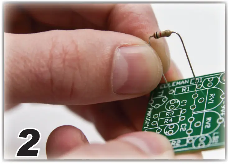
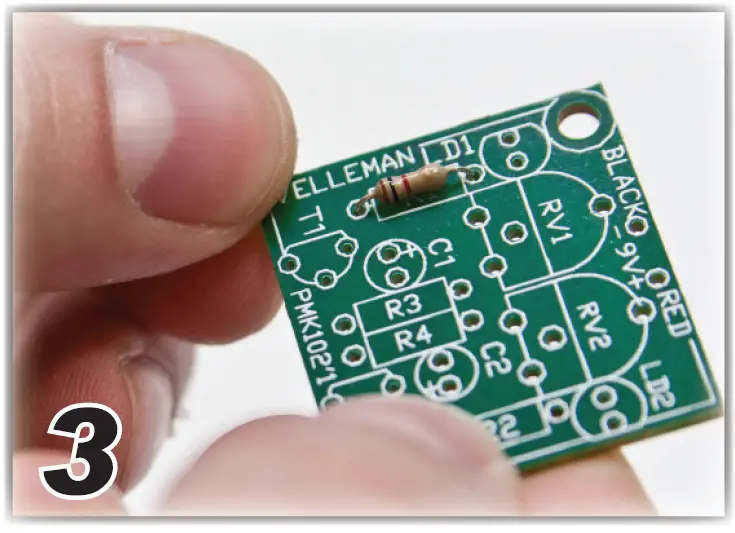
- Insert part against PCB

- Insert part against PCB

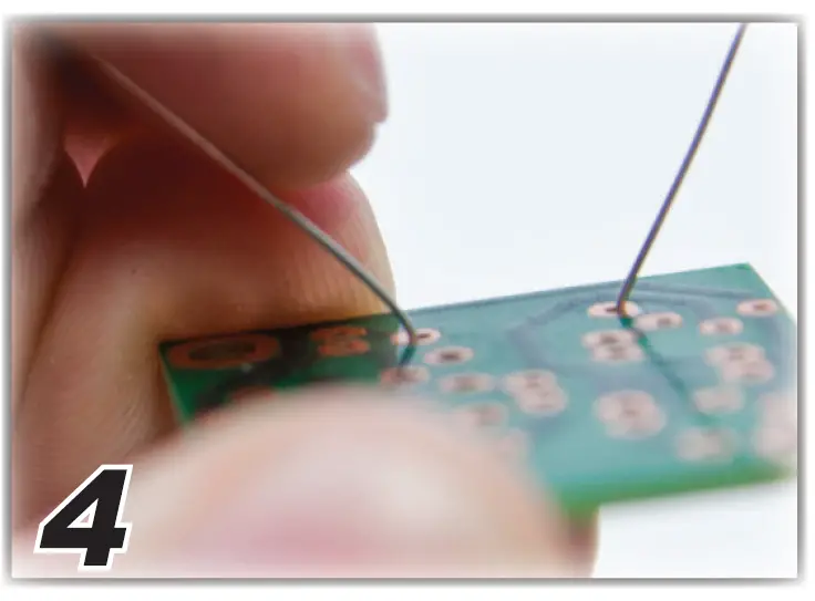
- Bend leads

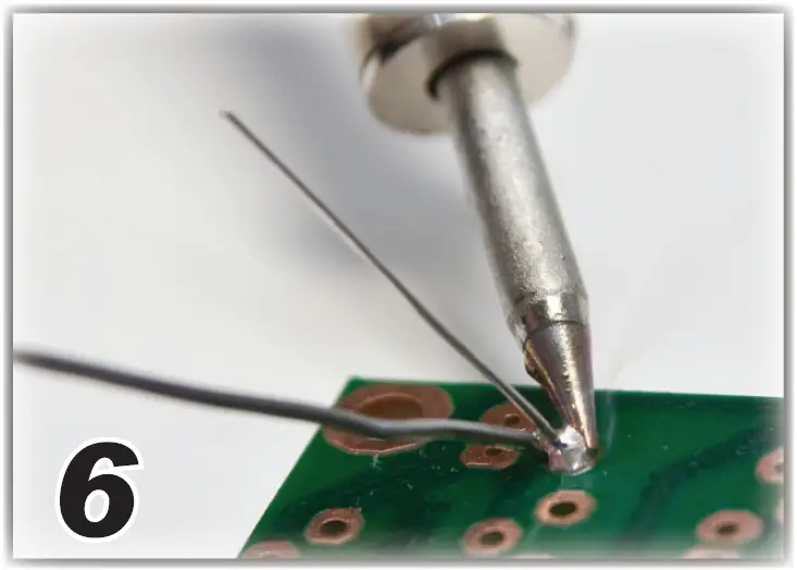
- Heat part lead & PCB pad

- Apply solder

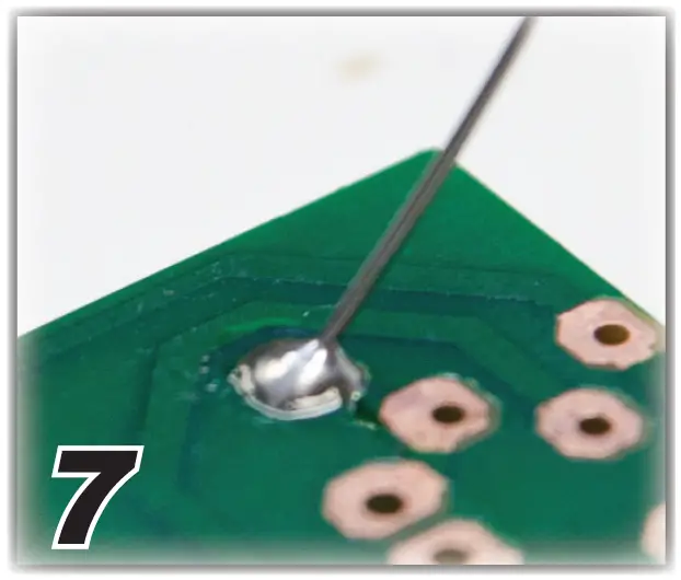
- Correct joint

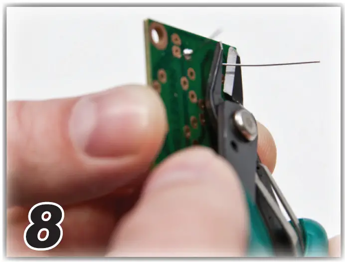
- Cut close to PCB

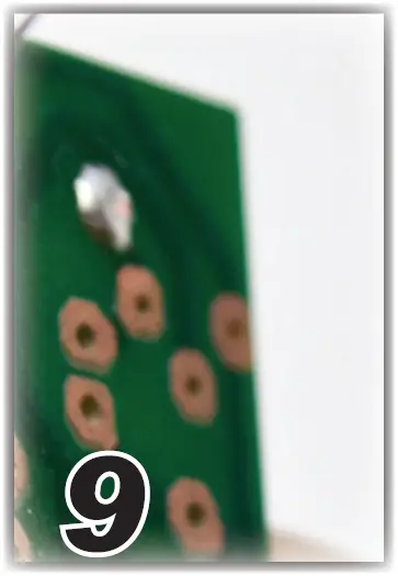
- Inspect

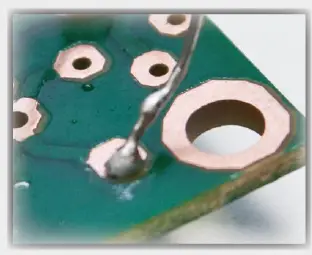
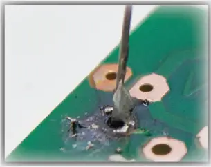
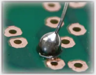
Bad solderings
- Too little solder

- Too much heat

- Bad contact

- Too much solder

not included


