Logic Group A/S
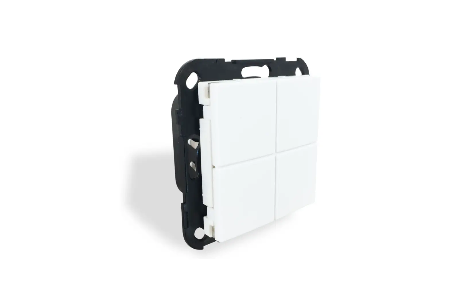
Dimmer Wall Switch
SKU: ZDB5400


Quickstart
This is a
secure
Wall Controller
for
.
To run this device please connect it to your mains power supply.
Important safety information
Please read this manual carefully. Failure to follow the recommendations in this manual may be dangerous or may violate the law.
The manufacturer, importer, distributor and seller shall not be liable for any loss or damage resulting from failure to comply with the instructions in this manual or any other material.
Use this equipment only for its intended purpose. Follow the disposal instructions.
Do not dispose of electronic equipment or batteries in a fire or near open heat sources.
What is Z-Wave?
Z-Wave is the international wireless protocol for communication in the Smart Home. This
device is suited for use in the region mentioned in the Quickstart section.

Z-Wave ensures a reliable communication by reconfirming every message (two-way
communication) and every mains powered node can act as a repeater for other nodes
(meshed network) in case the receiver is not in direct wireless range of the
transmitter.
This device and every other certified Z-Wave device can be used together with any other
certified Z-Wave device regardless of brand and origin as long as both are suited for the
same frequency range.
If a device supports secure communication it will communicate with other devices
secure as long as this device provides the same or a higher level of security.
Otherwise it will automatically turn into a lower level of security to maintain
backward compatibility.
For more information about Z-Wave technology, devices, white papers etc. please refer
to www.z-wave.info.
Product Description
The front is elegantly designed with a uniform diffused backlight in each square. The squares can light up in all colors which can be used to show the status of a lamp, as orientation light during nighttime, visual alarm and much more.Each square is a tactile switch that can hold up to four functions and control either a wired lamp or other Z-Wave devices, e.g. other light dimmers, roller shutters and power plugs. The pushbuttons can send ON, OFF and DIM commands to associated Z-Wave devices.The light dimmer can dim all dimmable light sources from 0-250 W.MATRIX 55 fits in standard 60mm CE boxes. Examples of compatible cover frames are GIRA System 55, Exxact and Elko Plus. The insert is also compatible with GIRA pushbutton sensor 2.
Prepare for Installation / Reset
Please read the user manual before installing the product.
In order to include (add) a Z-Wave device to a network it must be in factory default
state. Please make sure to reset the device into factory default. You can do this by
performing an Exclusion operation as described below in the manual. Every Z-Wave
controller is able to perform this operation however it is recommended to use the primary
controller of the previous network to make sure the very device is excluded properly
from this network.
Safety Warning for Mains Powered Devices
ATTENTION: only authorized technicians under consideration of the country-specific
installation guidelines/norms may do works with mains power. Prior to the assembly of
the product, the voltage network has to be switched off and ensured against re-switching.
Inclusion/Exclusion
On factory default the device does not belong to any Z-Wave network. The device needs
to be added to an existing wireless network to communicate with the devices of this network.
This process is called Inclusion.
Devices can also be removed from a network. This process is called Exclusion.
Both processes are initiated by the primary controller of the Z-Wave network. This
controller is turned into exclusion respective inclusion mode. Inclusion and Exclusion is
then performed doing a special manual action right on the device.
Quick trouble shooting
Here are a few hints for network installation if things dont work as expected.
- Make sure a device is in factory reset state before including. In doubt exclude before include.
- If inclusion still fails, check if both devices use the same frequency.
- Remove all dead devices from associations. Otherwise you will see severe delays.
- Never use sleeping battery devices without a central controller.
- Dont poll FLIRS devices.
- Make sure to have enough mains powered device to benefit from the meshing
Association – one device controls an other device
Z-Wave devices control other Z-Wave devices. The relationship between one device
controlling another device is called association. In order to control a different
device, the controlling device needs to maintain a list of devices that will receive
controlling commands. These lists are called association groups and they are always
related to certain events (e.g. button pressed, sensor triggers, …). In case
the event happens all devices stored in the respective association group will
receive the same wireless command wireless command, typically a ‘Basic Set’ Command.
Association Groups:
Group NumberMaximum NodesDescription
| 1 | 5 | Lifeline. Sends Device Reset notifications, and Central Scene notifications. |
| 2 | 5 | Sends Basic Report with information about the actual level for the dimmer. This report is used by other MATRIX devices that are used for controlling this dimmer. |
| 3 | 5 | Nodes in this group receive Switch Binary Set commands when pushbutton 1 is operated. It can be used for controlling other Z-Wave devices, e.g. a relay module. |
| 4 | 5 | Nodes in this group receive Multilevel Switch Set / Multi-Level Switch Start Level Change / Multi-Level Switch Stop Level Change when pushbuttons 1-4 are operated. It can, as an example, be used for controlling light dimmers. |
| 5 | 5 | Nodes in this group also receives Basic Report with the actual state of pushbutton 2. It can be used by other MATRIX devices to update their internal pushbutton states. Normally the state is reported by the controlled device, but in cases where this is not possible, the MATRIX devices can get synchronised by reporting to each other. |
| 6 | 5 | Nodes in this group receives Binary Switch Set commands when pushbutton 2 is operated. It can be used for controlling other Z-Wave devices, e.g. a relay module. |
| 7 | 5 | Nodes in this group receives Multi-Level Switch Set / Multi-Level Switch Start Level Change / Multi-Level Switch Stop Level Change when pushbutton 2 is operated. It can, as an example, be used for controlling light dimmers. |
| 8 | 5 | Nodes in this group also receives Basic Report with the actual state of pushbutton 3. It can be used by other MATRIX devices to update their internal pushbutton states. Normally the state is reported by the controlled device, but in cases where this is not possible, the MATRIX devices can get synchronised by reporting to each other. |
| 9 | 5 | Nodes in this group receives Binary Switch Set commands when pushbutton 3 is operated. It can be used for controlling other Z-Wave devices, e.g. a relay module. |
| 10 | 5 | Nodes in this group receives Multi-Level Switch Set / Multi-Level Switch Start Level Change / Multi-Level Switch Stop Level Change when pushbutton 3 is operated. It can, as an example, be used for controlling light dimmers. |
| 11 | 5 | Nodes in this group also receives Basic Report with the actual state of pushbutton 4. It can be used by other MATRIX devices to update their internal pushbutton states. Normally the state is reported by the controlled device, but in cases where this is not possible, the MATRIX devices can get synchronised by reporting to each other. |
| 12 | 5 | Nodes in this group receives Binary Switch Set commands when pushbutton 4 is operated. It can be used for controlling other Z-Wave devices, e.g. a relay module. |
| 13 | 5 | Nodes in this group receives Multi-Level Switch Set / Multi-Level Switch Start Level Change / Multi-Level Switch Stop Level Change when pushbutton 4 is operated. It can, as an example, be used for controlling light dimmers. |
| 14 | 5 | Sends Basic Report with information about the actual level for the dimmer. This report is used by other MATRIX devices that are used for controlling this dimmer. |
Configuration Parameters
Z-Wave products are supposed to work out of the box after inclusion, however
certain configuration can adapt the function better to user needs or unlock further
enhanced features.
IMPORTANT: Controllers may only allow configuring
signed values. In order to set values in the range 128 … 255 the value sent in
the application shall be the desired value minus 256. For example: To set a
parameter to 200 it may be needed to set a value of 200 minus 256 = minus 56.
In case of a two byte value the same logic applies: Values greater than 32768 may
needed to be given as negative values too.
This parameter specifies which pushbutton(s) that shall be used to control the built-in dimmer.The parameter is a bitmask, so each of the values can be added together in order to have several pushbuttons to operate the dimmer.
Size: 1 Byte, Default Value: 1
SettingDescription
| 0 | No local operation of the dimmer. |
| 1 | Pushbutton 1 controls the dimmer. |
| 2 | Pushbutton 2 controls the dimmer. |
| 4 | Pushbutton 3 controls the dimmer. |
| 8 | Pushbutton 4 controls the dimmer. |
Parameter 10: Enhanced LED control
This parameter can be used for enabling the enhanced LED control. See document about MATRIX enhanced LED control.
Size: 1 Byte, Default Value: 0
SettingDescription
| 0 | Enhanced LED control is disabled. |
| 1 | Enhanced LED control is enabled. |
Pushbutton input debounce time in 0.01 seconds resolution.
Size: 1 Byte, Default Value: 5
SettingDescription
| 0 – 255 | 02.55 seconds. Default is 5, which equals to a debounce-filter on 50 milliseconds (0.05 seconds) |
Specifies the time that a pushbutton must be activated before it is detected as pressed. Resolution is in 0.01 seconds.
Size: 1 Byte, Default Value: 20
SettingDescription
| 0 – 255 | 02.55 seconds. Default is 20, which equals to 200 milliseconds (0.2 seconds). |
Specifies the time that a pushbutton must have been activated before it is accepted as held-down. Resolution is 0.01 seconds.
Size: 1 Byte, Default Value: 50
SettingDescription
| 0 – 255 | 02.55 seconds. Default is 50, which equals to 500 milliseconds (0,5 seconds). |
Parameter 14: Global brightness control
This parameter specifies a common brightness for each of the three base colours for all four pushbutton indicators.Byte 1: Red brightness. Byte 2: Green brightness. Byte 3: Blue brightness. Byte 4: Not usedmust be set to 0.
Size: 4 Byte, Default Value: 255
SettingDescription
| 0 – 255 | Byte 3: Brightness level for the blue colour in the 4 indicator groups. (Default is 255) |
| 0 | Byte 4: Not usedmust be set to 0. |
| 0 – 255 | Byte1: Brightness level for the red colour in the 4 indicator groups. (Default is 255) |
| 0 – 255 | Byte 2: Brightness level for the green colour in the 4 indicator groups. (Default is 255) |
Parameter 15: Associations groups, transmission when included secure
This parameter specifies if commands are transmitted as a secure message for each of the association groups.This parameter is only used when the device is included in security mode (either S0 or S2). The values are bitmasks that can be added up to select several options.
Size: 2 Byte, Default Value: 8191
SettingDescription
| 0 | All messages in all groups are sent as insecure. |
| 1 | Messages in association group 2 is sent as secure. |
| 2 | Messages in association group 3 is sent as secure. |
| 4 | Messages in association group 4 is sent as secure. |
| 8 | Messages in association group 5 is sent as secure. |
| 16 | Messages in association group 6 is sent as secure. |
| 32 | Messages in association group 7 is sent as secure. |
| 64 | Messages in association group 8 is sent as secure. |
| 128 | Messages in association group 9 is sent as secure. |
| 256 | Messages in association group 10 is sent as secure. |
| 512 | Messages in association group 11 is sent as secure. |
| 1024 | Messages in association group 12 is sent as secure. |
| 2048 | Messages in association group 13 is sent as secure. |
| 4096 | Messages in association group 14 is sent as secure. |
| 8191 | Messages in all association groups are sent as secure. |
This parameter specifies the functionality of pushbutton 1.
Size: 1 Byte, Default Value: 0
SettingDescription
| 0 | Standard toggle-function, the state is switched between on and off, dimming up and down. |
| 1 | Automatic turn off after the time has expired (staircase lighting function), the time is specified in the next configuration parameter. |
| 2 | Automatic turn on after the time has expired, the time is specified in the next configuration parameter. |
| 3 | Always turn off or dim down . Using this parameter, the pushbutton can only send off or dim down commands. Use this in pair with another pushbutton with value 4 (see chapter 2.6 in the manual) |
| 4 | Always turn on or dim up. Using this parameter, the pushbutton can only send on or dim up commands. Use this in pair with another pushbutton with value 3 (see chapter 2.6 in the manual) |
This parameter specifies the time used in previous configuration parameter. This parameter is only applicable if previous parameter has value 1 or 2.
Size: 2 Byte, Default Value: 300
SettingDescription
| 0 – 43200 | Specifies the time in seconds. Default is 300 = 5 minutes. |
Byte 1: Enable / DisableByte 2: Upper switch valueByte 3: Lower switch valueByte 4: Not usedmust be set to 0.
Size: 1 Byte, Default Value: 0
SettingDescription
| 0 | Byte 1: DisabledA single activation of the button will not result in commands are sent to devices in association group 4. |
| 0 – 99 | Byte 2: When single pressing the button for ON, a Multilevel Switch Set with this value will be send to devices in association group 4. |
| 0 – 99 | Byte 3: When single pressing the button for OFF, a Multilevel Switch Set with this value will be send to devices in association group 4. (Default = 0) |
| 0 | Byte 4: Not usedmust be set to 0 |
| 1 | Byte 1: EnabledA single activation will result in commands are sent to devices in association group 4, they will receive commands with the values set below. (Default). |
| 255 | Byte 2: When single pressing the button for ON, a Multilevel Switch Set with this value will be send to devices in association group 4. (Default = 255) |
This parameter specifies how received Binary Switch Set commands are handled.
Size: 1 Byte, Default Value: 0
SettingDescription
| 0 | Binary Switch Set only controls the pushbutton indicator LEDs, ON/OFF |
| 1 | Binary Switch Set controls the internal switch status and the pushbutton indicator LEDs |
| 2 | Binary Switch Set is handled as if the user had activated the pushbutton, including transmission of commands via the association groups |
Parameter 2: Duration of dimming
This parameter specifies the duration of a full regulation of the light from 0% to 100%. A regulation of the light with 1% will take 1/100 of the specified duration. This is used when a pushbutton is held-down for controlling the dimming, and when the dimming is fulfilled from other Z-Wave devices.
Size: 1 Byte, Default Value: 5
SettingDescription
| 0 | Immediately |
| 1 – 127 | Duration in seconds. |
| 128 – 255 | Duration in minutes (minus 127) from 1128 minutes, where 128 is 1 minute |
This parameter specifies how the LED indication is controlled.
Size: 1 Byte, Default Value: 7
SettingDescription
| 0 | Internal LED control is disabled, only external commands control the indication |
| 1 | The LED indication follows the switch status |
| 2 | The LED indication follows the switch statuswith inverted functionality |
| 3 | Same as 1 |
| 4 | Same as 2 |
| 5 | The LED indication follows the status of the internal dimmer, ON or OFF |
| 6 | The LED indication follows the status of the internal dimmer with inverted functionality, ON or OFF |
| 7 | The LED indicator is ON for 5 seconds when the pushbutton is activated |
This parameter specifies how Command Class Switch Color commands are handled.
Size: 1 Byte, Default Value: 1
SettingDescription
| 0 | Direct control; the LED indication shows the received colour immediately, until the pushbutton is activated |
| 1 | Colour command sets the colour for OFF indication |
| 2 | Colour command sets the colour for ON indication |
This parameter specifies the saturation levels for the red, green and blue LEDs, when ON status is indicated. (Default is the ON-state indicated by a 50% blue colour).Byte 1: Colour saturation, red.Byte 2: Colour saturation, green.Byte 3: Colour saturation, blue.Byte 4: LED control.
Size: 4 Byte, Default Value: 255
SettingDescription
| 0 – 255 | Byte 4: LED indicator control; see the application note about this parameter. (Default is 0) |
| 0 – 255 | Byte 1: Specifies the saturation for the red LEDs. (Default is 0) |
| 0 – 255 | Byte 2: Specifies the saturation for the green LEDs. (Default is 0) |
| 0 – 255 | Byte 3: Specifies the saturation for the blue LEDs. (Default is 127) |
This parameter specifies the saturation levels for the red, green and blue LEDs, when OFF status is indicated. (Default is the OFF-state indicated as a low white light on 5%).Byte 1: Colour saturation, red.Byte 2: Colour saturation, green.Byte 3: Colour saturation, blue.Byte 4: LED control.
Size: 4 Byte, Default Value: 47
SettingDescription
| 0 – 255 | Byte 3: Specifies the saturation for the blue LEDs. (Default is 47) |
| 0 – 255 | Byte 4: LED indicator control; see the application note about this parameter. (Default is 0) |
| 0 – 255 | Byte 1: Specifies the saturation for the red LEDs. (Default is 47) |
| 0 – 255 | Byte 2: Specifies the saturation for the green LEDs. (Default is 47) |
This parameter specifies the functionality of pushbutton 2.
Size: 1 Byte, Default Value: 0
SettingDescription
| 0 | Standard toggle-function, the state is switched between on and off, dimming up and down. |
| 1 | Automatic turn off after the time has expired (staircase lighting function), the time is specified in the next configuration parameter. |
| 2 | Automatic turn on after the time has expired, the time is specified in the next configuration parameter. |
| 3 | Always turn off or dim down. Using this parameter, the pushbutton can only send off or dim down commands. Use this in pair with another pushbutton with value 4 (see chapter 2.6 in the manual) |
| 4 | Always turn on or dim up. Using this parameter, the pushbutton can only send on or dim up commands. Use this in pair with another pushbutton with value 3 (see chapter 2.6 in the manual) |
This parameter specifies the time used in previous configuration parameter. This parameter is only applicable if previous parameter has value 1 or 2.
Size: 2 Byte, Default Value: 300
SettingDescription
| 0 | Enhanced LED control is disabled |
| 0 – 43200 | Specifies the time in seconds. Default is 300 = 5 minutes |
| 1 | Enhanced LED control is enabled |
Byte 1: Enable / Disable.Byte 2: Upper switch value.Byte 3: Lower switch value.Byte 4: Not usedmust be set to 0.
Size: 4 Byte, Default Value: 0
SettingDescription
| 0 | Byte 1: DisabledA single activation of the pushbutton will not send commands to devices in association group 4 |
| 0 | Byte 4: Not usedmust be set to 0. |
| 0 – 99 | Byte 3: When single pressing the pushbutton for OFF, a Multilevel Switch Set with this value will be send to devices in association group 4. (Default = 0) |
| 0 – 99 | Byte 2: When single pressing the pushbutton for ON, a Multilevel Switch Set with this value will be send to devices in association group 4. (Default = 255) |
| 1 | Byte 1: EnabledA single activation will send commands to devices in association group 4. Devices will receive commands with the values set in Byte 2 and 3 (Default) |
| 255 | Byte 2: When single pressing the pushbutton for ON, a Multilevel Switch Set with this value will be send to devices in association group 4. (Default = 255) |
This parameter specifies how received Binary Switch Set commands are handled.
Size: 1 Byte, Default Value: 0
SettingDescription
| 0 | Binary Switch Set only controls the button indicator LEDs, ON/OFF |
| 1 | Binary Switch Set controls the internal switch status and the button indicator LEDs |
| 2 | Binary Switch Set is handled as if the user had activated the button, including transmission of commands via the association groups |
This parameter specifies how the LED indication is controlled.
Size: 1 Byte, Default Value: 7
SettingDescription
| 0 | Internal LED control is disabled, only external commands control the indication |
| 1 | The LED indication follows the switch status |
| 2 | The LED indication follows the switch statuswith inverted functionality |
| 3 | Same as 1 |
| 4 | Same as 2 |
| 5 | The LED indication follows the status of the internal dimmer, ON or OFF |
| 6 | The LED indication follows the status of the internal dimmer with inverted functionality, ON or OFF |
| 7 | The LED indicator is ON for 5 seconds when the pushbutton is activated |
This parameter specifies how Command Class Switch Color commands is handled.
Size: 1 Byte, Default Value: 1
SettingDescription
| 0 | Direct control; the LED indication shows the received colour immediately, until the pushbutton is activated |
| 1 | Colour command sets the colour for OFF indication |
| 2 | Colour command sets the colour for ON indication |
Parameter 3: Duration of on/off
This parameter specifies the duration when turning the light on or off.
Size: 1 Byte, Default Value: 0
SettingDescription
| 0 | Immediately |
| 1 – 127 | Time in seconds |
| 128 – 255 | Time in minutes (minus 127) from 1128 minutes, where 128 is 1 minute |
This parameter specifies the saturation levels for the red, green and blue LEDs, when ON status is indicated. (Default is the ON-state indicated by a 50% blue colour).Byte 1: Colour saturation, red.Byte 2: Colour saturation, green.Byte 3: Colour saturation, blue.Byte 4: LED control.
Size: 4 Byte, Default Value: 0
SettingDescription
| 0 – 255 | Byte 1:Specifies the saturation for the red LEDs. (Default is 0) |
| 0 – 255 | Byte 2: Specifies the saturation for the green LEDs. (Default is 0) |
| 0 – 255 | Byte 3: Specifies the saturation for the blue LEDs. (Default is 127) |
| 0 – 255 | Byte 4: LED indicator control; see the application note about this parameter. (Default is 0) |
This parameter specifies the saturation levels for the red, green and blue LEDs, when OFF status is indicated. (Default is the OFF-state indicated as a low white light on 5%).Byte 1: Colour saturation, red.Byte 2: Colour saturation, green.Byte 3: Colour saturation, blue.Byte 4: LED control.
Size: 4 Byte, Default Value: 255
SettingDescription
| 0 – 255 | Byte 4: LED indicator control; see the application note about this parameter (Default is 0) |
| 0 – 255 | Byte 2: Specifies the saturation for the green LEDs (Default is 47) |
| 0 – 255 | Byte 3: Specifies the saturation for the blue LEDs (Default is 47) |
| 0 – 255 | Byte 1: Specifies the saturation for the red LEDs (Default is 47) |
This parameter specifies the functionality of pushbutton 3.
Size: 1 Byte, Default Value: 0
SettingDescription
| 0 | Standard toggle-function, the state is switched between on and off, dimming up and down |
| 1 | Automatic turn off after the time has expired (staircase lighting function), the time is specified in the next configuration parameter. |
| 2 | Automatic turn on after the time has expired, the time is specified in the next configuration parameter. |
| 3 | Always turn off or dim down. Using this parameter, the pushbutton can only send off or dim down commands. Use this in pair with another pushbutton with value 4 (see chapter 2.6 in the manual) |
| 4 | Always turn on or dim up. Using this parameter, the pushbutton can only send on or dim up commands. Use this in pair with another pushbutton with value 3 (see chapter 2.6 in the manual) |
This parameter specifies the time used in previous configuration parameter. This parameter is only applicable if previous parameter has value 1 or 2.
Size: 2 Byte, Default Value: 300
SettingDescription
| 0 – 43200 | Specifies the time in seconds. Default is 300 = 5 minutes |
Byte 1: Enable / Disable.Byte 2: Upper switch value.Byte 3: Lower switch value.Byte 4: Not usedmust be set to 0.
Size: 4 Byte, Default Value: 0
SettingDescription
| 0 | Byte 4: Not usedmust be set to 0 |
| 0 – 99 | Byte 3: When single pressing the pushbutton for OFF, a Multilevel Switch Set with this value will be send to devices in association group 4 (Default = 0) |
| 0 | Byte 1: DisabledA single activation of the pushbutton will not send commands to devices in association group 4 |
| 0 – 99 | Byte 2: When single pressing the pushbutton for ON, a Multilevel Switch Set with this value will be send to devices in association group 4 |
| 1 | Byte 1: EnabledA single activation will send commands to devices in association group 4. Devices will receive commands with the values set in Byte 2 and 3 (default) |
| 255 | Byte 2: When single pressing the pushbutton for ON, a Multilevel Switch Set with this value will be send to devices in association group 4 (default) |
This parameter specifies how received Binary Switch Set commands are handled.
Size: 1 Byte, Default Value: 0
SettingDescription
| 0 | Binary Switch Set only controls the pushbutton indicator LEDs, ON/OFF |
| 1 | Binary Switch Set controls the internal switch status and the pushbutton indicator LEDs |
| 2 | Binary Switch Set is handled as if the user had activated the pushbutton, including transmission of commands via the association groups |
This parameter specifies how the LED indication is controlled.
Size: 1 Byte, Default Value: 7
SettingDescription
| 0 | Internal LED control is disabled, only external commands control the indication |
| 1 | The LED indication follows the switch status |
| 2 | The LED indication follows the switch statuswith inverted functionality |
| 3 | Same as 1 |
| 4 | Same as 2 |
| 5 | The LED indication follows the status of the internal dimmer, ON or OFF |
| 6 | The LED indication follows the status of the internal dimmer with inverted functionality, ON or OFF |
| 7 | The LED indicator is ON for 5 seconds when the pushbutton is activated |
This parameter specifies how Command Class Switch Color commands is handled
Size: 1 Byte, Default Value: 1
SettingDescription
| 0 | Direct control; the LED indication shows the received colour immediately, until the pushbutton is activated |
| 1 | Colour command sets the colour for OFF indication |
| 2 | Colour command sets the colour for ON indication |
This parameter specifies the saturation levels for the red, green and blue LEDs, when ON status is indicated. (Default is the ON-state indicated by a 50% blue colour).Byte 1: Colour saturation, red.Byte 2: Colour saturation, green.Byte 3: Colour saturation, blue.Byte 4: LED control.
Size: 4 Byte, Default Value: 127
SettingDescription
| 0 – 255 | Byte 1: Specifies the saturation for the red LEDs. (Default is 0) |
| 0 – 255 | Byte 3: Specifies the saturation for the blue LEDs. (Default is 127) |
| 0 – 255 | Byte 2: Specifies the saturation for the green LEDs. (Default is 0) |
| 0 – 255 | Byte 4: LED indicator control; see the application note about this parameter. (Default is 0) |
This parameter specifies the saturation levels for the red, green and blue LEDs, when OFF status is indicated. (Default is the OFF-state indicated as a low white light on 5%).Byte 1: Colour saturation, red.Byte 2: Colour saturation, green.Byte 3: Colour saturation, blue.Byte 4: LED control.
Size: 4 Byte, Default Value: 47
SettingDescription
| 0 – 255 | Byte 2: Specifies the saturation for the green LEDs. (Default is 47) |
| 0 – 255 | Byte 3: Specifies the saturation for the blue LEDs. (Default is 47) |
| 0 – 255 | Byte 4: LED indicator control; see the application note about this parameter. (Default is 0) |
| 0 – 255 | Byte 1: Specifies the saturation for the red LEDs. (Default is 47). |
Parameter 4: Dimmer mode
The dimmer can work in three different modes: on/off, leading edge or trailing edge.
Size: 1 Byte, Default Value: 1
SettingDescription
| 0 | No dimming, only on/off (0/100%). |
| 1 | Trailing edge dimming |
| 2 | Leading edge dimming |
This parameter specifies the functionality of pushbutton 4.
Size: 1 Byte, Default Value: 0
SettingDescription
| 0 | Standard toggle-function, the state is switched between on and off, dimming up and down |
| 1 | Automatic turn off after the time has expired (staircase lighting function), the time is specified in the next configuration parameter. |
| 2 | Automatic turn on after the time has expired, the time is specified in the next configuration parameter. |
| 3 | Always turn off or dim down. Using this parameter, the pushbutton can only send off or dim down commands. Use this in pair with another pushbutton with value 4 (see chapter 2.6 in the manual). |
| 4 | Always turn on or dim up. Using this parameter, the pushbutton can only send on or dim up commands. Use this in pair with another pushbutton with value 3 (see chapter 2.6 in the manual). |
This parameter specifies the time used in previous configuration parameter. This parameter is only applicable if previous parameter has value 1 or 2.
Size: 2 Byte, Default Value: 300
SettingDescription
| 0 – 43200 | Specifies the time in seconds. Default is 300 = 5 minutes |
Byte 1: Enable / Disable.Byte 2: Upper switch value.Byte 3: Lower switch value.Byte 4: Not usedmust be set to 0.
Size: 4 Byte, Default Value: 255
SettingDescription
| 0 | Byte 4: Not usedmust be set to 0. |
| 0 – 99 | Byte 2: When single pressing the pushbutton for ON, a Multilevel Switch Set with this value will be send to devices in association group 4 |
| 0 | Byte 1: DisabledA single activation of the pushbutton will not send commands to devices in association group 4. |
| 0 – 99 | Byte 3: When single pressing the pushbutton for OFF, a Multilevel Switch Set with this value will be send to devices in association group 4. (Default = 0) |
| 1 | Byte 1: EnabledA single activation will send commands to devices in association group 4. Devices will receive commands with the values set in Byte 2 and 3 (Default). |
| 255 | Byte 2: When single pressing the pushbutton for ON, a Multilevel Switch Set with this value will be send to devices in association group 4. (Default) |
This parameter specifies how received Binary Switch Set commands are handled.
Size: 1 Byte, Default Value: 2
SettingDescription
| 0 | Binary Switch Set only controls the pushbutton indicator LEDs, ON/OFF |
| 1 | Binary Switch Set controls the internal switch status and the pushbutton indicator LEDs |
| 2 | Binary Switch Set is handled as if the user had activated the pushbutton, including transmission of commands via the association groups |
This parameter specifies how the LED indication is controlled.
Size: 1 Byte, Default Value: 7
SettingDescription
| 0 | Internal LED control is disabled, only external commands control the indication. |
| 1 | The LED indication follows the switch status |
| 2 | The LED indication follows the switch statuswith inverted functionality |
| 3 | Same as 1 |
| 4 | Same as 2 |
| 5 | The LED indication follows the status of the internal dimmer, ON or OFF |
| 6 | The LED indication follows the status of the internal dimmer with inverted functionality, ON or OFF |
| 7 | The LED indicator is ON for 5 seconds when the pushbutton is activated |
This parameter specifies how Command Class Switch Color commands are handled.
Size: 1 Byte, Default Value: 1
SettingDescription
| 0 | Direct control; the LED indication shows the received colour immediately, until the pushbutton is activated |
| 1 | Colour command sets the colour for OFF indication |
| 2 | Colour command sets the colour for ON indication |
This parameter specifies the saturation levels for the red, green and blue LEDs, when ON status is indicated. (Default is the ON-state indicated by a 50% blue colour).Byte 1: Colour saturation, red.Byte 2: Colour saturation, green.Byte 3: Colour saturation, blue.Byte 4: LED control.
Size: 4 Byte, Default Value: 255
SettingDescription
| 0 – 255 | Byte 1: Specifies the saturation for the red LEDs. (Default is 0) |
| 0 – 255 | Byte 2: Specifies the saturation for the green LEDs. (Default is 0) |
| 0 – 255 | Byte 3: Specifies the saturation for the blue LEDs. (Default is 127) |
| 0 – 255 | Byte 4: LED indicator control; see the application note about this parameter. (Default is 0) |
This parameter specifies the saturation levels for the red, green and blue LEDs, when OFF status is indicated. (Default is the OFF-state indicated as a low white light on 5%).Byte 1: Colour saturation, red.Byte 2: Colour saturation, green.Byte 3: Colour saturation, blue.Byte 4: LED control.
Size: 4 Byte, Default Value: 255
SettingDescription
| 0 – 255 | Byte 1: Specifies the saturation for the red LEDs. (Default is 47) |
| 0 – 255 | Byte 2: Specifies the saturation for the green LEDs. (Default is 47) |
| 0 – 255 | Byte 4: LED indicator control; see the application note about this parameter. (Default is 0) |
| 0 – 255 | Byte 3: Specifies the saturation for the blue LEDs. (Default is 47) |
Parameter 5: Dimmer minimum level
This parameter specifies the actual level of the dimmer output when set to 0%.
Size: 1 Byte, Default Value: 0
SettingDescription
| 0 – 99 | Corresponds to 099% |
Parameter 6: Dimmer maximum level
This parameter specifies the actual level of the dimmer output when set to 99%.
Size: 1 Byte, Default Value: 99
SettingDescription
| 0 – 99 | Corresponds to 099% |
Parameter 7: Central Scene notifications
This parameter can be used for disabling Central Scene notifications.
Size: 1 Byte, Default Value: 1
SettingDescription
| 0 | Notifications are disabled |
| 1 | Notifications are enabled |
Parameter 8: Double-activation functionality
This parameter specifies the reaction when double-activating the pushbuttons.
Size: 1 Byte, Default Value: 1
SettingDescription
| 0 | Double-activation disabled |
| 1 | Double-activation sets light to 100% |
This parameter can be used for disabling the Z-Wave network add/remove process when triple-activating pushbutton 1. If disabled, the triple-activation functionality can be used as a Central Scene notification.
Size: 1 Byte, Default Value: 1
SettingDescription
| 0 | Triple-activation of pushbutton 1, does not start the add/remove process. |
| 1 | Triple-activation of pushbutton 1, starts the add/remove process |
Technical Data
| Hardware Platform | ZM5101 |
| Device Type | Wall Controller |
| Network Operation | Always On Slave |
| Firmware Version | HW: 1 FW: 1.01 |
| Z-Wave Version | 6.81.03 |
| Certification ID | ZC10-19096765 |
| Z-Wave Product Id | 0x0234.0x0003.0x0124 |
| Color | White |
| IP (Ingress Protection) Rated | ok |
| Switch Type | Push Button Illuminated |
| Z-Wave Scene Type | Central Scene |
| Firmware Updatable | Updatable by Consumer via Internet |
| Electric Load Type | Dimmable ELV (Magnetic)Dimmable FluorescentDimmable LEDDimmable MLV (Magnetic) |
| Neutral Wire Required | ok |
| Security V2 | S2_UNAUTHENTICATED ,S2_AUTHENTICATED |
| Frequency | XXfrequency |
| Maximum transmission power | XXantenna |
Supported Command Classes
- Association Grp Info
- Association V2
- Basic V2
- Central Scene V3
- Configuration V3
- Device Reset Locally
- Firmware Update Md V4
- Manufacturer Specific V2
- Multi Channel Association V3
- Multi Channel V4
- Powerlevel
- Security
- Security 2
- Supervision
- Switch Binary
- Switch Color
- Switch Multilevel V4
- Transport Service V2
- Version V3
- Zwaveplus Info V2
Controlled Command Classes
- Switch Binary
- Switch Multilevel V4
Explanation of Z-Wave specific terms
- Controller — is a Z-Wave device with capabilities to manage the network.
Controllers are typically Gateways,Remote Controls or battery operated wall controllers. - Slave — is a Z-Wave device without capabilities to manage the network.
Slaves can be sensors, actuators and even remote controls. - Primary Controller — is the central organizer of the network. It must be
a controller. There can be only one primary controller in a Z-Wave network. - Inclusion — is the process of adding new Z-Wave devices into a network.
- Exclusion — is the process of removing Z-Wave devices from the network.
- Association — is a control relationship between a controlling device and
a controlled device. - Wakeup Notification — is a special wireless message issued by a Z-Wave
device to announces that is able to communicate. - Node Information Frame — is a special wireless message issued by a
Z-Wave device to announce its capabilities and functions.


 Zds-210na Manual")

 Zds-220na Manual")


