
FIBARO
FIBARO KeyFob
SKU: FIBEFGKF-601


Quickstart
This is a
secure
Handheld Controller
for
Europe.
To run this device please insert fresh 1 * CR2450 3.0V batteries.
Please make sure the internal battery is fully charged.
1) Place the KeyFob within the direct range of your Z-Wave controller.
2) Set the main Z-Wave controller in (security/non-security) add mode (see the controller’s manual).
3) Press any button three times.
4) Wait for the adding process to end.
5) Successful adding will be confirmed by the Z-Wave controller’s message and green LED colour.
Important safety information
Please read this manual carefully. Failure to follow the recommendations in this manual may be dangerous or may violate the law.
The manufacturer, importer, distributor and seller shall not be liable for any loss or damage resulting from failure to comply with the instructions in this manual or any other material.
Use this equipment only for its intended purpose. Follow the disposal instructions.
Do not dispose of electronic equipment or batteries in a fire or near open heat sources.
What is Z-Wave?
Z-Wave is the international wireless protocol for communication in the Smart Home. This
device is suited for use in the region mentioned in the Quickstart section.

Z-Wave ensures a reliable communication by reconfirming every message (two-way
communication) and every mains powered node can act as a repeater for other nodes
(meshed network) in case the receiver is not in direct wireless range of the
transmitter.
This device and every other certified Z-Wave device can be used together with any other
certified Z-Wave device regardless of brand and origin as long as both are suited for the
same frequency range.
If a device supports secure communication it will communicate with other devices
secure as long as this device provides the same or a higher level of security.
Otherwise it will automatically turn into a lower level of security to maintain
backward compatibility.
For more information about Z-Wave technology, devices, white papers etc. please refer
to www.z-wave.info.
Product Description
FIBARO KeyFob is a Z-Wave Plus compatible, battery-powered, compact remote control. Six buttons allow you to control other devices through the Z-Wave network and run various scenes defined in FIBARO System. Configure actions for one, two, three clicks and holding the button to suit all your needs. Built-in locking system will ensure that unauthorized person will not take control of your home.
Prepare for Installation / Reset
Please read the user manual before installing the product.
In order to include (add) a Z-Wave device to a network it must be in factory default
state. Please make sure to reset the device into factory default. You can do this by
performing an Exclusion operation as described below in the manual. Every Z-Wave
controller is able to perform this operation however it is recommended to use the primary
controller of the previous network to make sure the very device is excluded properly
from this network.
Reset to factory default
This device also allows to be reset without any involvement of a Z-Wave controller. This
procedure should only be used when the primary controller is inoperable.
There are two ways of resetting the device:
1) Press O and – simultaneously.
2) Press Δ or X until LED glows yellow.
3) Press + to confirm.
• Resetting on start-up
1) Remove the battery.
2) Hold O and + while inserting the battery.
Safety Warning for Batteries
The product contains batteries. Please remove the batteries when the device is not used.
Do not mix batteries of different charging level or different brands.
Inclusion/Exclusion
On factory default the device does not belong to any Z-Wave network. The device needs
to be added to an existing wireless network to communicate with the devices of this network.
This process is called Inclusion.
Devices can also be removed from a network. This process is called Exclusion.
Both processes are initiated by the primary controller of the Z-Wave network. This
controller is turned into exclusion respective inclusion mode. Inclusion and Exclusion is
then performed doing a special manual action right on the device.
Inclusion
Press any button three times.
Exclusion
1) Press O and – simultaneously.
2) Press Δ or X until LED glows green.
3) Press + to confirm.
Product Usage
Menu:
4. LED will pulse twice with same colour as selected menu position to confirm completing action.
Lock Mode
Lock Mode will be disabled when:
• menu is available, but without option of resetting the device.
Setting the unlocking sequence using advanced parameter:
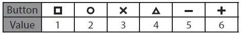
+ 512 * Value of third button + 4096 * Value of third button
4. Wait for the device to configure.
Setting time to lock and locking button using advanced” parameter:
1. Calculate value of parameter using table and formula:
Value of parameter = Time to lock in seconds +
4. Wait for the device to configure.
Setting a new sequence using advanced parameter:
1. Calculate value of parameter using table and formula:
4. Wait for the device to configure.
and activating a triple click will introduce delay to a double click reaction.
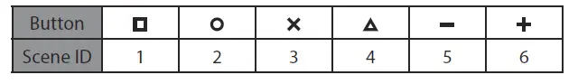
Scene IDs of buttons:
Battery:
KeyFob can be powered with CR2450 (included) battery. Estimated” battery life with device added once, default settings, direct range and” maximum 5 pushes per day is 2 years.
Replacing the battery: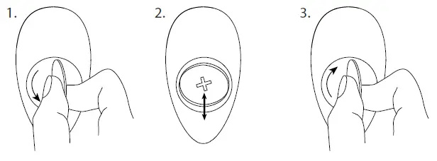
Communication to a Sleeping device (Wakeup)
This device is battery operated and turned into deep sleep state most of the time
to save battery life time. Communication with the device is limited. In order to
communicate with the device, a static controller C is needed in the network.
This controller will maintain a mailbox for the battery operated devices and store
commands that can not be received during deep sleep state. Without such a controller,
communication may become impossible and/or the battery life time is significantly
decreased.
This device will wakeup regularly and announce the wakeup
state by sending out a so called Wakeup Notification. The controller can then
empty the mailbox. Therefore, the device needs to be configured with the desired
wakeup interval and the node ID of the controller. If the device was included by
a static controller this controller will usually perform all necessary
configurations. The wakeup interval is a tradeoff between maximal battery
life time and the desired responses of the device. To wakeup the device please perform
the following action:
To wake up the device press O and + simultaneously or use 1st menu position:
2) Press Δ or X until LED glows white.
3) Press + to confirm.
Quick trouble shooting
Here are a few hints for network installation if things dont work as expected.
- Make sure a device is in factory reset state before including. In doubt exclude before include.
- If inclusion still fails, check if both devices use the same frequency.
- Remove all dead devices from associations. Otherwise you will see severe delays.
- Never use sleeping battery devices without a central controller.
- Dont poll FLIRS devices.
- Make sure to have enough mains powered device to benefit from the meshing
Association – one device controls an other device
Z-Wave devices control other Z-Wave devices. The relationship between one device
controlling another device is called association. In order to control a different
device, the controlling device needs to maintain a list of devices that will receive
controlling commands. These lists are called association groups and they are always
related to certain events (e.g. button pressed, sensor triggers, …). In case
the event happens all devices stored in the respective association group will
receive the same wireless command wireless command, typically a ‘Basic Set’ Command.
Association Groups:
Group NumberMaximum NodesDescription
| 1 | 1 | Lifeline – reports the device status and allows for assigning single device only (main controller by default). |
| 2 | 5 | Square – On/Off – is assigned to clicking the square button and is used to turn on/off associated devices. |
| 3 | 5 | Square – Multilevel – is assigned to clicking and holding the square button and is used to turn on/off and change level of associated devices. |
| 4 | 5 | Circle – On/Off – is assigned to clicking the circle button and is used to turn on/off associated devices. |
| 5 | 5 | Circle – Multilevel – is assigned to clicking and holding the circle button and is used to turn on/off and change level of associated devices. |
| 6 | 5 | Cross – On/Off – is assigned to clicking the cross button and is used to turn on/off associated devices. |
| 7 | 5 | Cross – Multilevel – is assigned to clicking and holding the cross” button and is used to turn on/off and change level of associated devices. |
| 8 | 5 | Triangle – On/Off – is assigned to clicking the triangle button and is used to turn on/off associated devices. |
| 9 | 5 | Triangle – Multilevel – is assigned to clicking and holding the triangle button and is used to turn on/off and change level of associated devices. |
| 10 | 5 | Minus – On/Offu201d is assigned to clicking the minus” button and is used to turn on/off associated devices. |
| 11 | 5 | Minus – Multilevel – is assigned to clicking and holding the minus” button and is used to turn on/off and change level of associated devices. |
| 12 | 5 | Plus – On/Off – is assigned to clicking the plus button and is used to turn on/off associated devices. |
| 13 | 5 | Plus – Multilevel – is assigned to clicking and holding the plus button and is used to turn on/off and change level of associated devices. |
Configuration Parameters
Z-Wave products are supposed to work out of the box after inclusion, however
certain configuration can adapt the function better to user needs or unlock further
enhanced features.
IMPORTANT: Controllers may only allow configuring
signed values. In order to set values in the range 128 … 255 the value sent in
the application shall be the desired value minus 256. For example: To set a
parameter to 200 it may be needed to set a value of 200 minus 256 = minus 56.
In case of a two byte value the same logic applies: Values greater than 32768 may
needed to be given as negative values too.
Parameter 1: Lock Mode activation
This parameter allows to activate Lock Mode and set up unlocking sequence. Device will lock after time set in parameter 2 or after pressing and holding selected button. See (Lock Mode) on page 9 of the manual for more information.
Size: 2 Byte, Default Value: 0
SettingDescription
| 0 | Lock Mode disabled |
| 9 – 28086 | unlocking sequence |
This parameter allows to set time that must elapse from the last press of the button to lock the device and locking button. Setting locking button will deactivate associations and scenes for pressing and holding the selected button. This parameter is irrelevant if parameter 1 is set to 0 (Lock Mode disable).See (Lock Mode) on page 9 of the manual for more information.
Size: 2 Byte, Default Value: 60
SettingDescription
| 0 | Lock Mode disabled |
| 5 – 1791 | calculated value |
Parameter 3: First scene sequence
This parameter allows to set up sequence that activates scene with ID 7. See (Sequences) in the manual for more information.
Size: 2 Byte, Default Value: 0
SettingDescription
| 0 | 1st sequence disabled |
| 9 – 28086 | value of sequence |
Parameter 4: Second scene sequence
This parameter allows to set up sequence that activates scene with ID 8. See Sequences in the manual for more information.
Size: 2 Byte, Default Value: 0
SettingDescription
| 0 | 2nd sequence disabled |
| 9 – 28086 | value of sequence |
Parameter 5: Third scene sequence
This parameter allows to set up sequence that activates scene with ID 9. See Sequences in the manual for more information.
Size: 2 Byte, Default Value: 0
SettingDescription
| 0 | 3rd sequence disabled |
| 9 – 28086 | value of sequence |
Parameter 6: Fourth scene sequence
This parameter allows to set up sequence that activates scene with ID 10. See Sequences in the manual for more information.
Size: 2 Byte, Default Value: 0
SettingDescription
| 0 | 4th sequence disabled |
| 9 – 28086 | value of sequence |
Parameter 7: Fifth scene sequence
This parameter allows to set up sequence that activates scene with ID 11. See Sequences in the” manual for more information.
Size: 2 Byte, Default Value: 0
SettingDescription
| 0 | 5th sequence disabled |
| 9 – 28086 | value of sequence |
Parameter 8: Sixth scene sequence
This parameter allows to set up sequence that activates scene with ID 12. See Sequences in the manual for more information.
Size: 2 Byte, Default Value: 0
SettingDescription
| 0 | 6th sequence disabled |
| 9 – 28086 | value of sequence |
Parameter 9: Sequences – timeout
This parameter allows to set time that must elapse from the last press of the button to check if the sequence is valid.
Size: 1 Byte, Default Value: 10
SettingDescription
| 5 – 30 | 0,5 – 3s time to lock (0,1) |
This parameter allows to choose operating mode for single button associations.
Size: 1 Byte, Default Value: 0
SettingDescription
| 0 | single press switches state to opposite |
| 1 | single press switches state to opposite, double press sets to maximum level |
| 2 | single press turns on, double press turns off |
Parameter 11: Value sent to Square association group
This parameter allows to set value sent to devices in association group. It will result in turning multilevel devices on with set or last level. Value is irrelevant for simple on/off devices.
Size: 2 Byte, Default Value: 255
SettingDescription
| 1 – 99 | Forcing level of associated devices |
| 255 | setting associated devices to the last remembered state or turning them on |
Parameter 12: Value sent to Cicle association group
This parameter allows to set value sent to devices in association group. It will result in turning multilevel devices on with set or last level. Value is irrelevant for simple on/off devices.
Size: 2 Byte, Default Value: 255
SettingDescription
| 1 – 99 | forcing level of associated devices |
| 255 | setting associated devices to the last remembered state or turning them on |
Parameter 13: Value sent to Cross association group
This parameter allows to set value sent to devices in association group. It will result in turning multilevel devices on with set or last level. Value is irrelevant for simple on/off devices.
Size: 2 Byte, Default Value: 255
SettingDescription
| 1 – 99 | forcing level of associated devices |
| 255 | setting associated devices to the last remembered state or turning them on |
Parameter 14: Value sent to Triangel association group
This parameter allows to set value sent to devices in association group. It will result in turning multilevel devices on with set or last level. Value is irrelevant for simple on/off devices.
Size: 2 Byte, Default Value: 255
SettingDescription
| 1 – 99 | forcing level of associated devices |
| 255 | setting associated devices to the last remembered state or turning them on |
Parameter 15: Value sent to Minus association group
This parameter allows to set value sent to devices in association group. It will result in turning multilevel devices on with set or last level. Value is irrelevant for simple on/off devices.
Size: 2 Byte, Default Value: 255
SettingDescription
| 1 – 99 | forcing level of associated devices |
| 255 | setting associated devices to the last remembered state or turning them on |
Parameter 16: Value sent to Plus association group
This parameter allows to set value sent to devices in association group. It will result in turning multilevel devices on with set or last level. Value is irrelevant for simple on/off devices.
Size: 2 Byte, Default Value: 255
SettingDescription
| 1 – 99 | forcing level of associated devices |
| 255 | setting associated devices to the last remembered state or turning them on |
This parameter allows to activate paired buttons association mode for Square and Circle” buttons. Paired buttons are dependent and association are sent only to Square” groups. Circle” turns devices on and increases value, Square turns them off and decreases value.
Size: 1 Byte, Default Value: 0
SettingDescription
| 0 | paired buttons association inactive |
| 1 | paired buttons association active |
This parameter allows to activate paired buttons association mode for Cross” and Triangle” buttons. Paired buttons are dependent and association are sent only to Cross” groups. Triangle turns devices on and increases value, Cross” turns them off and decreases value.
Size: 1 Byte, Default Value: 0
SettingDescription
| 0 | paired buttons association inactive |
| 1 | paired buttons association active |
This parameter allows to activate paired buttons association mode for Minus” and Plus” buttons. Paired buttons are dependent and association are sent only to Minus” groups. Plus turns devices on and increases value, Minus” turns them off and decreases value.”
Size: 1 Byte, Default Value: 0
SettingDescription
| 0 | paired buttons association inactive |
| 1 | paired buttons association active |
This parameter determines which actions result in sending assigned scene IDs and attributes to the controller.
NOTE: Parameter values may be combined, e.g. 1+2=3 means that pressing button once or twice will result in sending assigned scene ID.
Size: 1 Byte, Default Value: 9
SettingDescription
| 1 | Key Pressed 1 time |
| 2 | Key Pressed 2 times |
| 4 | Key Pressed 3 times |
| 8 | Key Held Down & Released |
This parameter determines which actions result in sending assigned scene IDs and attributes to the controller.
NOTE:” Parameter values may be combined, e.g. 1+2=3 means that pressing button once or twice will result in sending assigned scene ID.
Size: 1 Byte, Default Value: 9
SettingDescription
| 1 | Key Pressed 1 time |
| 2 | Key Pressed 2 times |
| 4 | Key Pressed 3 times |
| 8 | Key Held Down & Released |
Parameter 29: Associations in Z-Wave network security mode
Parameter defines how commands are sent in specified association groups: as secure or non-secure. Parameter is active only in Z-Wave network security mode. It does not apply to 1st (Lifeline) association group.1
NOTE: Parameter 29 values may be combined, e.g. 1+2=3 means that 2nd & 3rd group are sent as secure.
Size: 2 Byte, Default Value: 4095
SettingDescription
| 1 | 2nd group sent as secure |
| 2 | 3rd group sent as secure |
| 4 | 4th group sent as secure |
| 8 | 5th group sent as secure |
| 16 | 6th group sent as secure |
| 32 | 7th group sent as secure |
| 64 | 8th group sent as secure |
| 128 | 9th group sent as secure |
| 256 | 10th group sent as secure |
| 512 | 11th group sent as secure |
| 1024 | 12th group sent as secure |
| 2048 | 13th group sent as secure |
Technical Data
| Dimensions | 70 x 38 x 15 mm |
| Weight | 30 gr |
| Hardware Platform | ZM5101 |
| EAN | 5905279987562 |
| Battery Type | 1 * CR2450 3.0V |
| Device Type | Handheld Controller |
| Network Operation | Portable Slave |
| Z-Wave Version | 6.51.09 |
| Certification ID | ZC10-16125346 |
| Z-Wave Product Id | 0x010F.0x1001.0x1000 |
| Frequency | Europe – 868,4 Mhz |
| Maximum transmission power | 5 mW |
Supported Command Classes
- Application Status
- Association Grp Info
- Association V2
- Battery
- Central Scene V3
- Configuration
- Crc 16 Encap
- Device Reset Locally
- Firmware Update Md V3
- Manufacturer Specific V2
- Multi Channel Association V2
- Powerlevel
- Protection V2
- Security
- Version V2
- Wake Up V2
- Zwaveplus Info V2
Controlled Command Classes
- Basic
- Switch Multilevel V3
Explanation of Z-Wave specific terms
- Controller — is a Z-Wave device with capabilities to manage the network.
Controllers are typically Gateways,Remote Controls or battery operated wall controllers. - Slave — is a Z-Wave device without capabilities to manage the network.
Slaves can be sensors, actuators and even remote controls. - Primary Controller — is the central organizer of the network. It must be
a controller. There can be only one primary controller in a Z-Wave network. - Inclusion — is the process of adding new Z-Wave devices into a network.
- Exclusion — is the process of removing Z-Wave devices from the network.
- Association — is a control relationship between a controlling device and
a controlled device. - Wakeup Notification — is a special wireless message issued by a Z-Wave
device to announces that is able to communicate. - Node Information Frame — is a special wireless message issued by a
Z-Wave device to announce its capabilities and functions.


 Fibefgpb-101-1 Manual")


