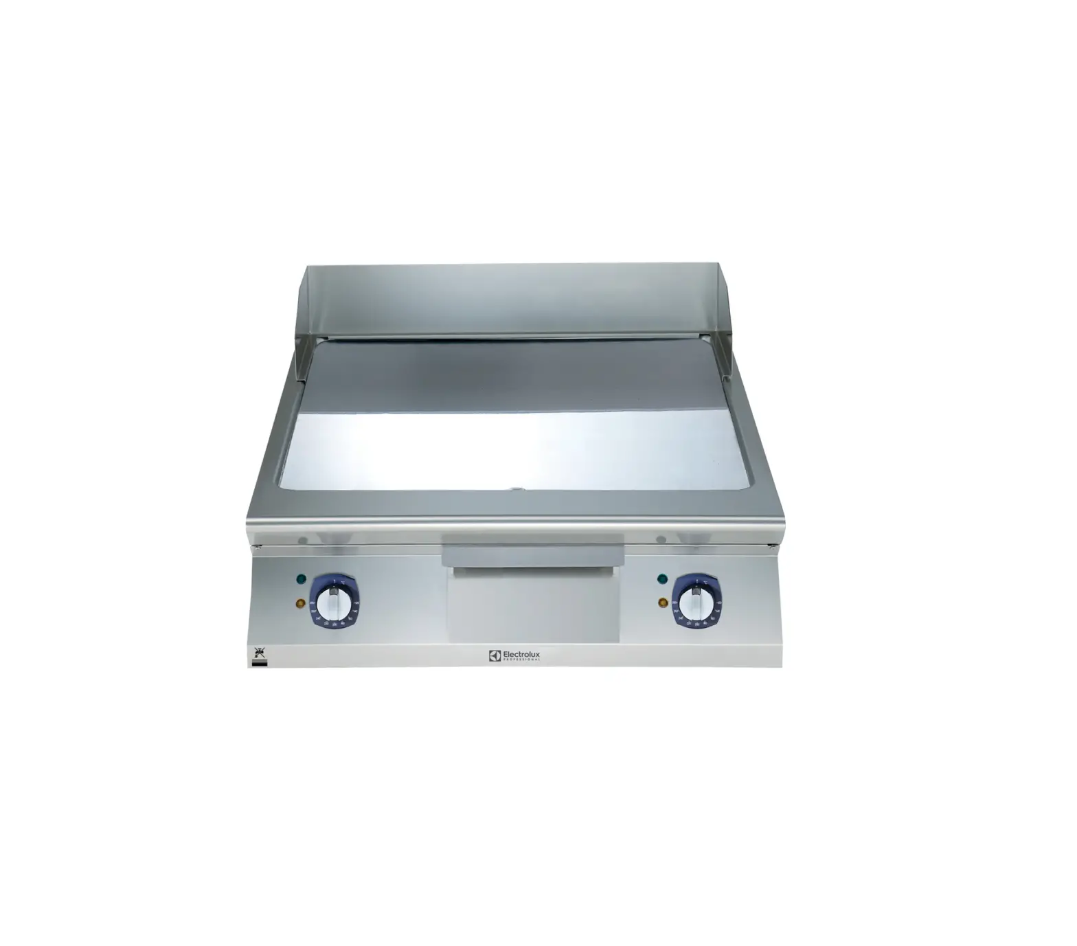
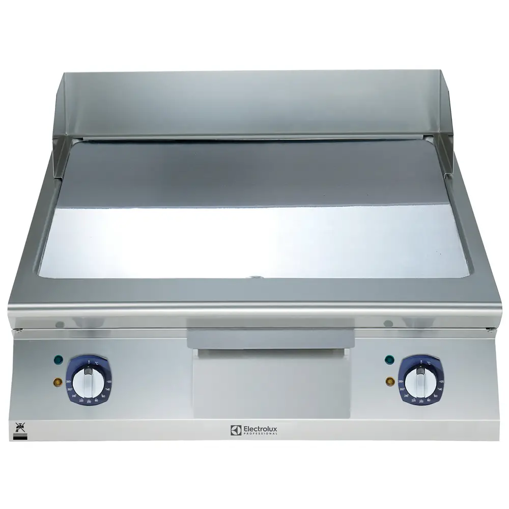
modular Cooking Range Line FRY TOP
 |
 |  |  |
MOD. | |||
| _60/30 FT…G _60/30 FT…G-CR _60/60 FT…G _60/60 FT…G-CR _60/30 FT…E _60/30 FT…E-CR _60/60 FT…E _60/60 FT…E-CR _60/30 FT…E-D _60/30 FT…E-CR-D _60/60 FT…E-D _60/60 FT…E-CR-D | _65/40 FT…G _65/40 FT…G-CR _65/40 FTGS _65/70 FT…G _65/70 FT…G-CR _65/70 FTGS _65/40 FT…E _65/40 FT…E-CR _65/40 FTES _65/70 FT…E _65/70 FT…E-CR _65/70 FTES _65/40 FT…E-D _65/40 FT…E-CR-D _65/70 FT…E-D _65/70 FT…E-CR-D | _70/40 FT…G… _70/40 FT…G-CR… _70/40 FTGS… _70/70 FT…G… _70/70 FT…G-CR… _70/70 FTGS… _70/40 FT…E… _70/40 FT…E-CR… _70/40 FTES… _70/70 FT…E… _70/70 FT…E-CR… _70/70 FTES… | _90/40 FT…G _90/40 FT…G-CR _90/80 FT…G _90/80 FT…G-CR _90/40 FT…E _90/40 FT…E-CR _90/80 FT…E _90/80 FT…E-CR |
| Doc.n° | 252.450.00 |
| Edition | 00 |
GENERAL PRESCRIPTIONS
| READ THIS MANUAL CAREFULLY. IT PROVIDES IMPORTANT INFORMATION FOR SAFE INSTALLATION, USE AND MAINTENANCE OF THE APPLIANCE. |
| FAILURE TO COMPLY WITH WHAT IS PRESENTED BELOW MAY COMPROMISE THE SAFETY OF THE EQUIPMENT. |
| THE MANUFACTURER WILL NOT BE LIABLE FOR ANY DAMAGE OR INJURY RESULTING FROM FAILURE TO OBSERVING THE FOLLOWING RULES. |
| TRANSLATION OF THE ORIGINAL INSTRUCTIONS. |
| APPLIANCES NEED PRECAUTIONS FOR INSTALLATION, PLACING AND/OR FIXATION AND CONNECTION TO THE MAINS. SEE SECTION “INSTALLATION INSTRUCTIONS”. |
| THE APPLIANCES NEED PRECAUTIONS FOR CLEANING. SEE THE SECTION ” INSTRUCTION FOR CLEANING”. |
 | THE SYMBOL” HIGH VOLTAGE” IS PLACED ON A PANEL THAT GIVES ACCESS TO A PART WITH HIGH VOLTAGE. |
| DO NOT CLEAN THE EQUIPMENT WITH DIRECTS WATER JETS, HIGH PRESSURE OR STEAM CLEANER. |
Keep this manual in a safe place, known to all users, so that it can be consulted throughout the working life of the appliance.
This equipment is designed for cooking food. It is intended for industrial use. Any other use is to be considered improper
This appliance is not intended for use by people (including children) with limited physical, sensory or mental abilities or without experience and knowledge of it.
Unless they are supervised or instructed in its use by a person responsible for their safety.
Do not leave de appliance unattended in presence of children and ensure that the latter do not have acces to the appliance.
The appliance must be used by trained personnel. Do not leave the appliance unattended when operating.
 | DO NOT STORE” AM MABLE MATERIALS IN CLOSE PROXIMITY TO THE APPLIANCE. FIRE HAZARD. |
The appliance must be installed in a well-ventilated room.
Inadequate ventilation causes asphyxia. Do not obstruct the ventilation system of the place where the appliance is installed. Do not obstruct the vents or ducts of this or other appliances.
The appliance must be installed in a well-ventilated room.
Inadequate ventilation causes asphyxia. Do not obstruct the ventilation system of the place where the appliance is installed. Do not obstruct the vents or ducts of this or other appliances.
In the event of an appliance fault or malfunction, shut the gas shut-off valve and/or switch the appliance off at the main switch installed upline. Installation and conversion to a different type of gas must be carried out by qualified technicians authorized by the manufacturer, in compliance with current safety standards and the instructions in this manual.
Appliance maintenance and conversion to a different type of gas must be carried out by qualified technicians authorized by the manufacturer, in compliance with current safety standards and the instructions in this manual.
Clean the appliance following the instructions given in Chapter” INSTRUCTIONS FOR CLEANING”.
DISPOSAL OF PACKING AND OF THE APPLIANCE
PACKING
The packing is made using environmentally friendly materials. The plastic recyclable components are:
– the transparent cover, the bags containing the instructions manual and nozzles (made of Polyethylene – PE).
– the straps (in Polypropylene – PP).
APPLIANCE
The appliance is manufactured 90% from recyclable metals (stainless steel, aluminium sheet, copper …. ) .
- The appliance must be scrapped in compliance with current regulations governing such disposal.
- Make the appliance unusable before scrapping.
- It must be disposed of properly.
| THE SYMBOL SHOWING A CROSSED-OUT WASTE CONTAINER ON THE UNIT OR PACKAGE INDICATES THAT, AT THE END JF ITS LIFE CYCLE, THE PRODUCT MUST 3E COLLECTED SEPARATE FROM OTHER WASTE. THE DIFFERENTIATED COLLECTION OF THIS EQUIPMENT IS ORGANISED AND MANAGED BY THE PRODUCER. THE USER WHO INTENDS TO GET RID OF THIS EQUIPMENT SHALL CONTACT THE PRODUCER AND FOLLOW THE SYSTEM THAT THE LATTER HAS USED IN ORDER TO COLLECT THE EQUIPMENT SEPARATELY AT THE END OF ITS LIFE. ABUSIVE DISPOSAL OF THE PRODUCT BY THE HOLDER WILL RESULT IN THE APPLICATION OF PENALTIES AS PER CURRENT STANDARDS. |
SAFETY DEVICES
ELECTRIC FRY-TOP
SAFETY THERMOSTAT
| THE MANUFACTURER WILL NOT BE LIABLE FOR ANY DAMAGE OR INJURY RESULTING FROM FAILURE TO OBSERVING THE FOLLOWING RULES. |
- The appliance is equipped with a manual reset safety thermostat that interrupts heating when the operating temperature exceeds the maximum permitted value.
- To restore appliance operation, remove the control panel and press the thermostat reset button. This procedure must only be carried out by a qualified, authorized technician.
INSTRUCTIONS FOR INSTALLATION
REMINDERS FOR THE INSTALLER
| READ THIS MANUAL CAREFULLY. IT PROVIDES IMPORTANT INFORMATION FOR SAFE INSTALLATION, USE AND MAINTENANCE OF THE APPLIANCE. |
| FAILURE TO COMPLY WITH WHAT IS PRESENTED BELOW MAY COMPROMISE THE SAFETY OF THE EQUIPMENT. |
| THE MANUFACTURER WILL NOT BE LIABLE FOR ANY DAMAGE OR INJURY RESULTING FROM FAILURE TO OBSERVING THE FOLLOWING RULES. |
Identify the specific appliance model. The modelnumber is detailed on the packing and on the appliance dataplate.
The appliance must be installed in a well-ventilated room.
Installation and conversion to a different type of gas must be carried out by qualified technicians authorized by the manufacturer, in compliance with current safety standards and the instructions in this manual.
Appliance maintenance and conversion to a different type of gas must be carried out by qualified technicians authorized by the manufacturer, in compliance with current safety standards and the instructions in this manual.
Do not obstruct any air vents or drains present on the appliance.
Do not tamper with appliance components.
REFERENCE STANDARDS AND LAWS
- Install the appliance in accordance with the safety standards in force in the country.
UNPACKING
- Check the state of the packing and in the event of damage, ask the delivery person to inspect the goods.
- Remove the packing.
- Remove the protective film from the outer panels.
Use a suitable solvent to remove any residual adhesive from the panels.
POSITIONING
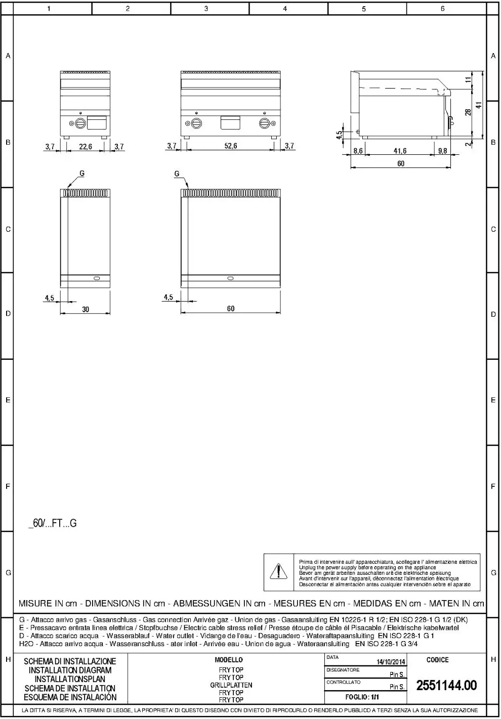
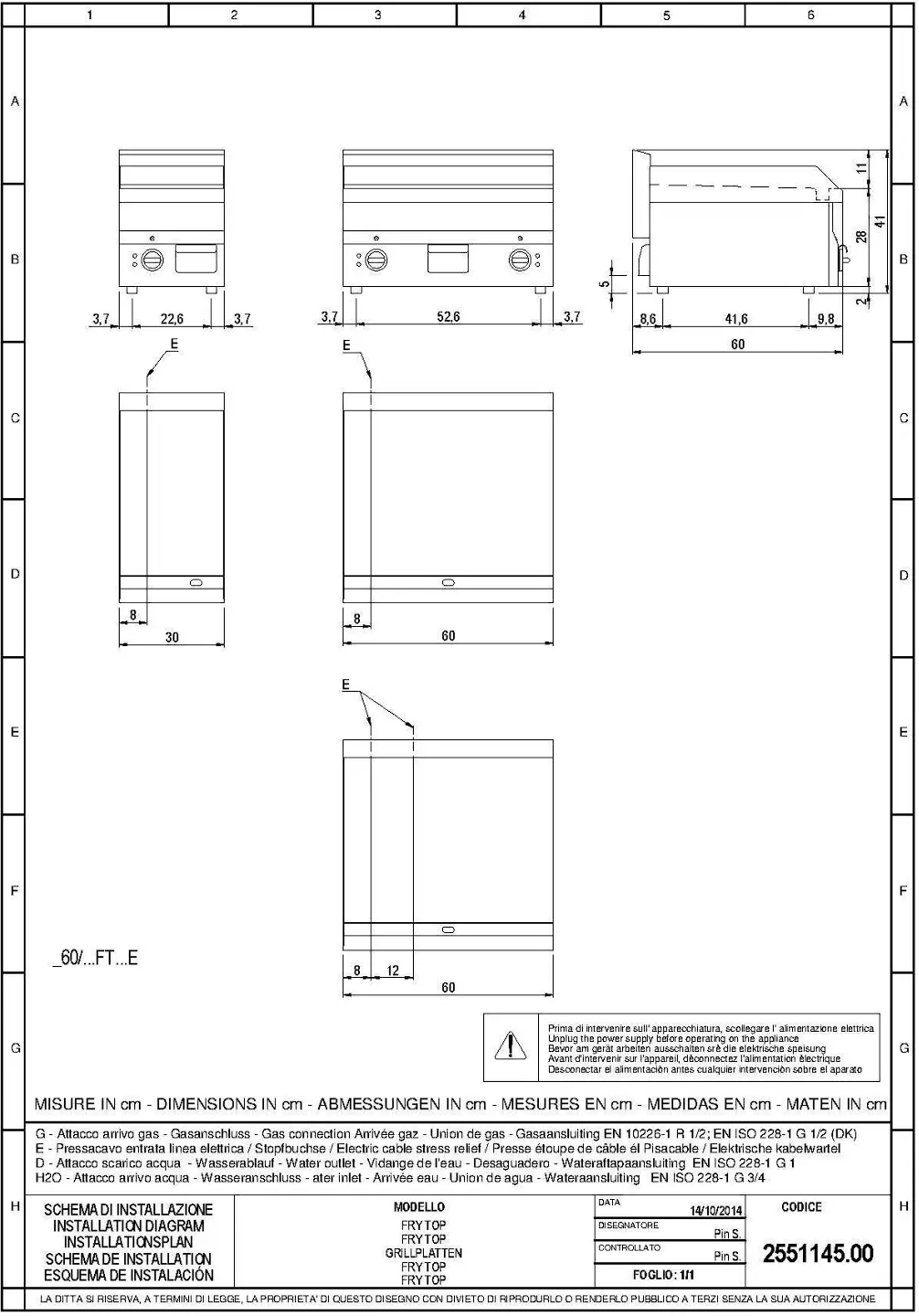
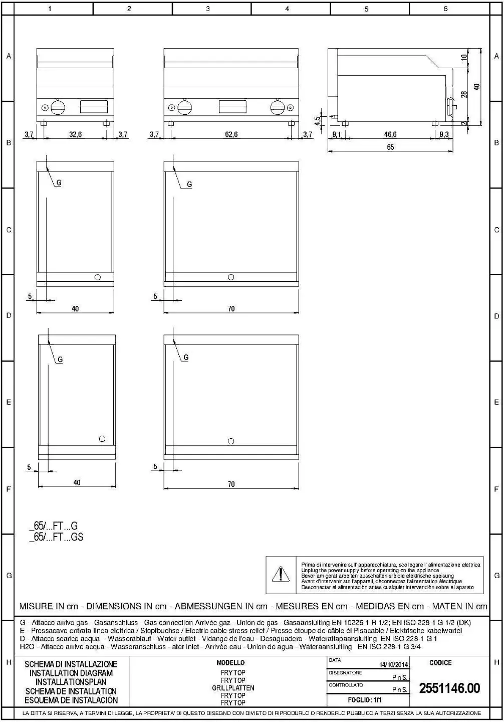
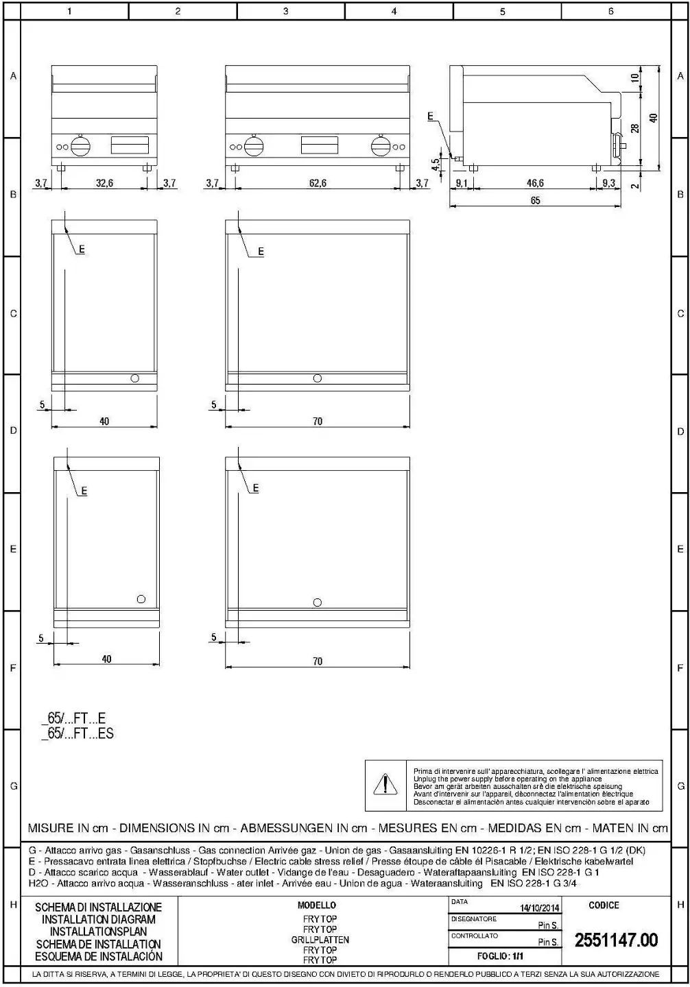
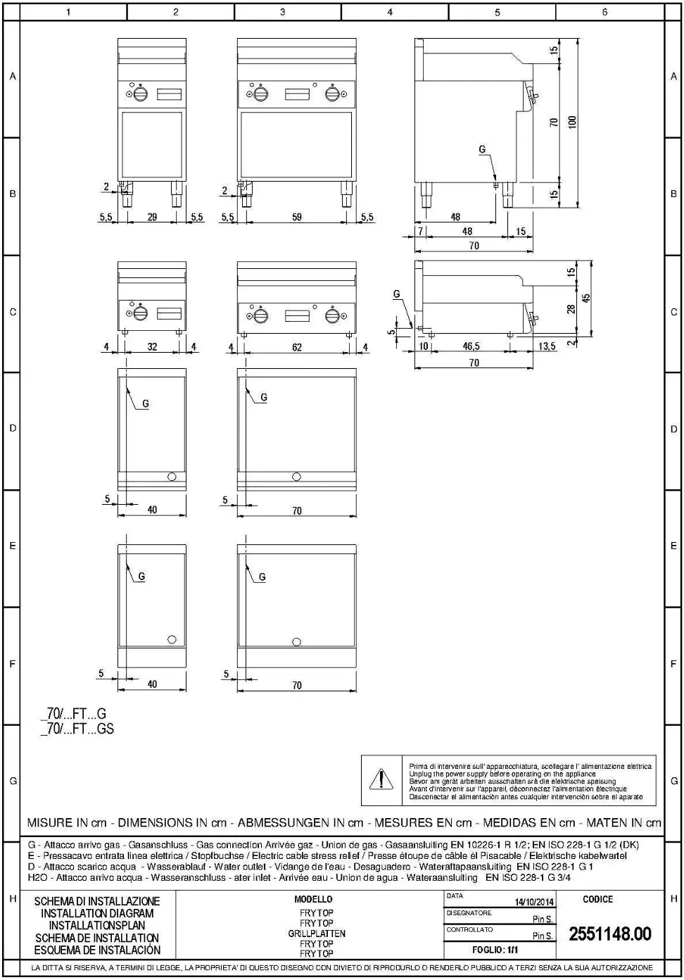
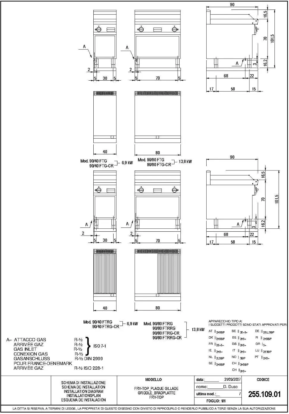
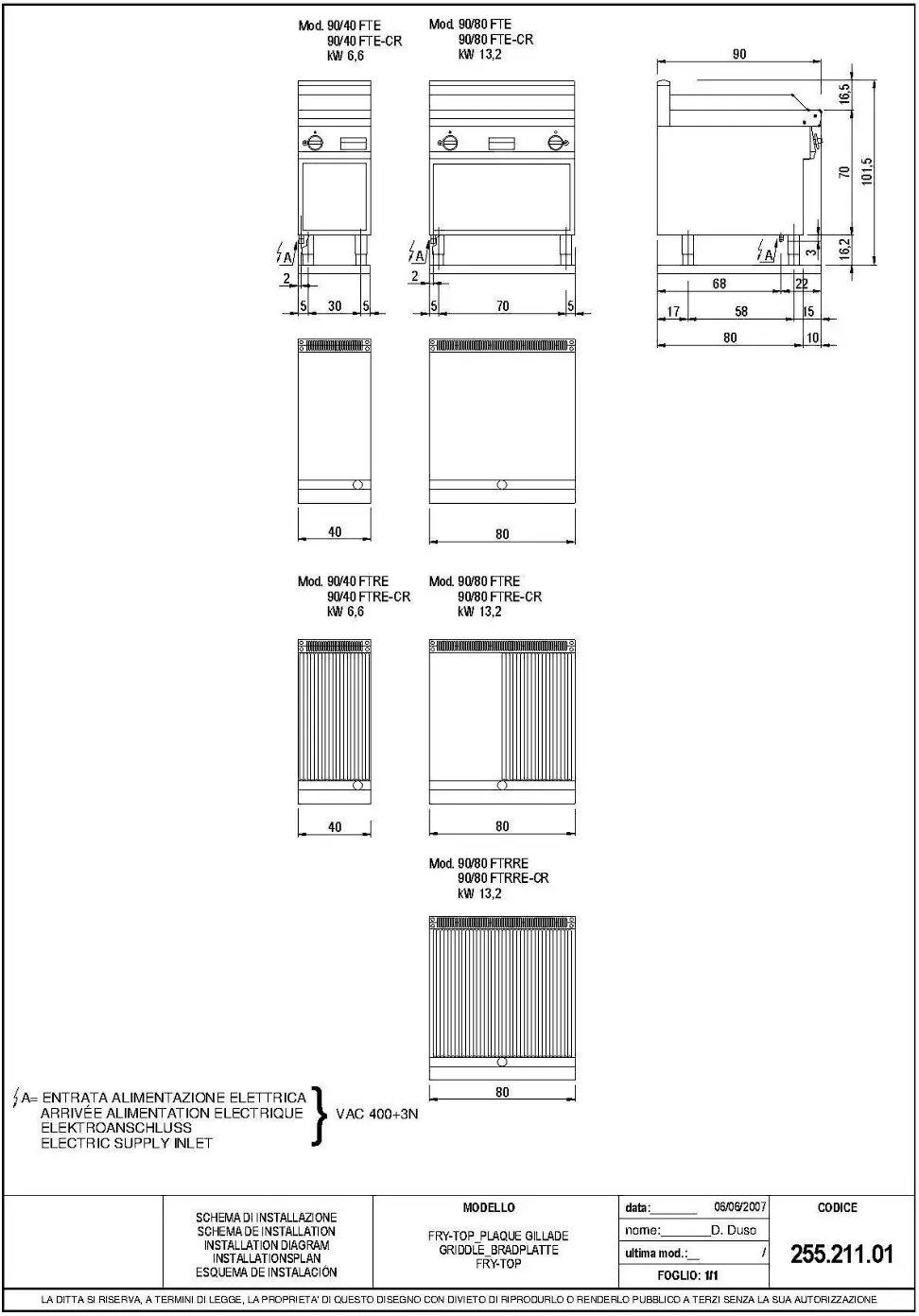
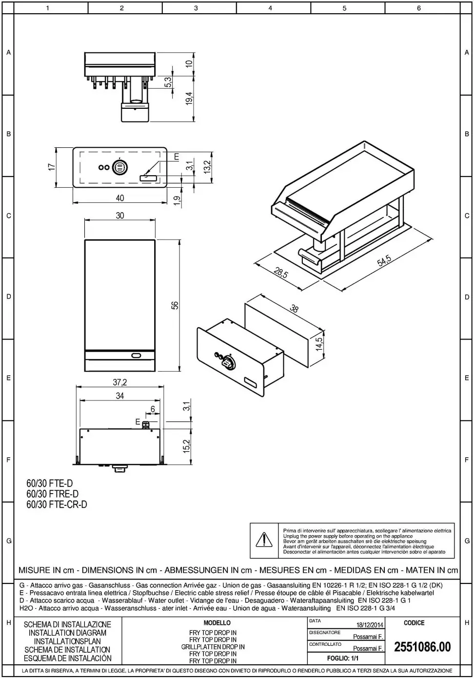
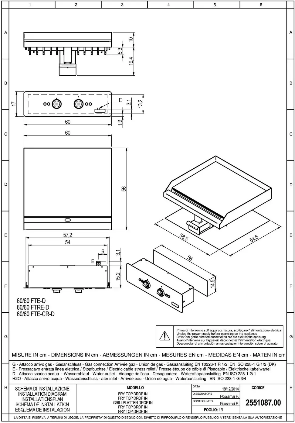
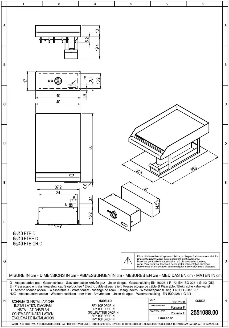
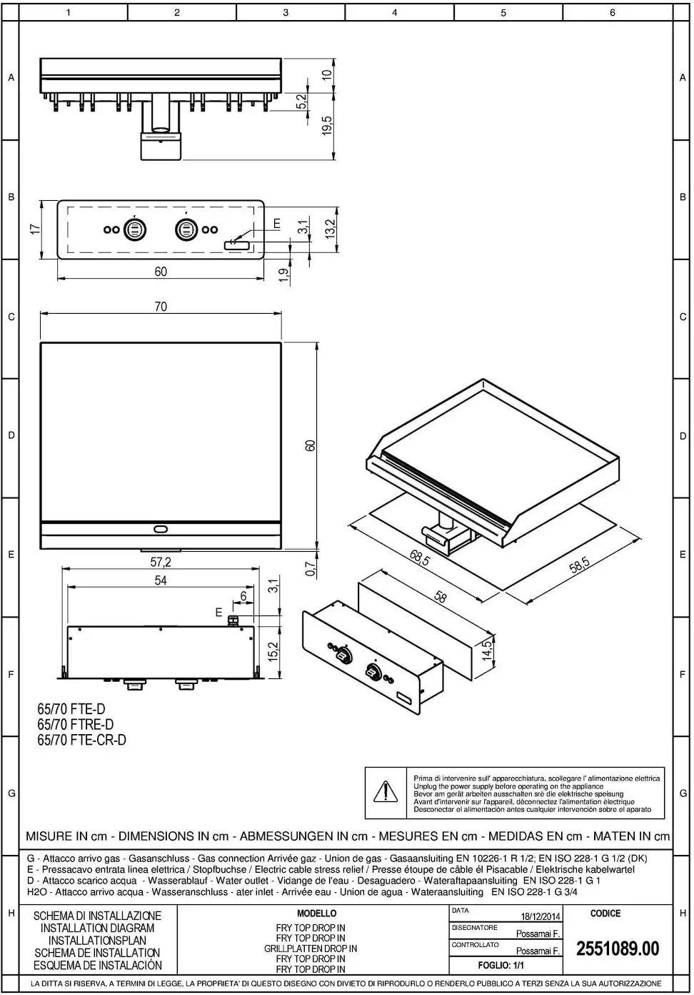
The overall dimensions of the appliance and the position of connections are given on the installation diagram at the end of this manual.
The appliance can be installed singly or in combination with other appliances in the same product range.
The appliance is not suitable for integrated installation.
Position the appliance at least 10 cm from adjacent walls.
If the appliance is to be be placed near walls, dividers, kitchen furniture, decorative elements etc.
this must be made of non-combustible materials Otherwise, they must be covered with suitable non-combustible heat insulating materials.
Level the appliance by means of the heightadjustable feet
APPLIANCE ASSEMBLY WITH BASE AND BRIDGE
Follow the instructions provided with the type of support utilized.
FUMES EXHAUST SYSTEM
Create a fumes exhaust system based on the ” Type ” of appliance. The ” Type ” is stated on the appliance dataplate.
“A1 ” TYPE APPLIANCE
Position the “A1” type appliance below an extractor hood to ensure smoke and fumes generated by cooking are removed.
” 821 ” TYPE APPLIANCE
Position the “B21” type appliance below an extractor hood.
” 811 ” TYPE APPLIANCE
Fit the “B11” type appliance with a suitable flue, available from the appliance manufacturer. Follow the assembly instructions provided with the flue.
Connect the flue to a 150/155 mm diameter hose, heat resistant to 300°C.
Vent to the outside or into an effi cient fl ue. The hose length must not exceed 3 metres.
CONNECTIONS
The position and dimensions of connections are given in the installation diagram at the end of this manual.
CONNECTION TO THE GAS SUPPLY
- Check that the appliance is designed to operate with the type of gas supply present on site. Check the information given on the decals on the packing and appliance.
- Convert the appliance to the local gas type, if necessary. Follow the instructions at the next paragraph “Conversion to a different type of gas”.
- On top appliances a rear connection is also available. Remove the plug present and screw it tightly onto the front connector.
- A rapid-action gas shut-off valve must be fitted upstream of the appliance in an easily accessible position.
- Do not use connection pipes having a diameter smaller than that of the appliance’s gas connector.
- Once the appliance has been installed, check for gas leaks at the connection points.
CONNECTION TO THE GAS SUPPLY
- Check that the appliance is designed to operatewith the type of gas supply present on site. Check the information given on the decals on the packing and appliance.
- Convert the appliance to the local gas type, if necessary. Follow the instructions at the next paragraph “Conversion to a different type of gas”.
- On top appliances a rear connection is also available. Remove the plug present and screw it tightly onto the front connector.
- A rapid-action gas shut-off valve must be fitted upstream of the appliance in an easily accessible position.
- Do not use connection pipes having a diameter smaller than that of the appliance’s gas connector.
- Once the appliance has been installed, check for gas leaks at the connection points.
ELECTRICAL CONNECTIONS
Check if the appliance is designed to operate at the voltage and frequency of the power supply present on site. Check the details given on the appliance data plate and plaque near the terminal board. Install upstream of the equipment in an easily accessible place, an all-pole disconnecting device with a contact gap of allowing full disconnection under the conditions of overvoltage category III.
A flexible rubber cable with insulation specifications not lower than type HOS RN-F must be used for connection.
Connect the power supply cable to the terminal board as shown in the wiring diagram supplied with the appliance.
Secure the power supply cable with the cable clamp.
Protect the power supply cable on the outside of the appliance with a rigid plastic or metal pipe.
If the power supply cable is damaged, it must be replaced by the manufacturer or his service centre or by a person with similar qualifications to prevent any risk.
| THE SYMBOL” HIGH VOLTAGE” IS PLACED ON A PANEL THAT GIVES ACCESS TO A PART WITH HIGH VOLTAGE. |
PROTECTIVE EARTH AND EARTH BONDING CONNECTIONS
Connect the appliance to an efficient ground circuit.
Connect the earth conductor to the terminal with the symbol ![]() next to the main terminal board.
next to the main terminal board.
Connect the metal structure of the appliance to the equipotential node. Connect the conductor to the terminal with the symbol ![]() on the outside part of the bottom.
on the outside part of the bottom.
CONNECTION TO THE WATER SUPPLY
- The appliance must be connected to a potable water supply. The water inlet pressure must be between 150 kPa and 300 kPa. Use a pressure reducer if the inlet pressure is above the maximum permitted level.
- Install a mechanical filter and a shut-off valve upstream of the appliance in an easily accessible point.
- Make sure the water circuit is free of ferrous particles before connecting the filter and the appliance.
- Seal any unused connectors with a plug.
- Once the appliance has been installed, check for gas leaks at the connection points.
CONNECTION TO THE WATER DRAIN
The water drainage system must be made using materials resistant to temperatures of 100 °C. The bottom of the appliance must not be subjected to steam produced by drainage of hot water.
Install a siphoned floor drain with grating below the water drain cock of Boiling pans and in front of Bratt pans.
 CONVERSION TO ANOTHER TYPE OF GAS
Table Tabl specifies:
– which gas can be used for the appliance.
– the nozzles and settings for each gas that can be used.
– For nozzles, the number indicated in table TAB1 is also stamped on the body of nozzles.
To convert the appliance to the local gas type, follow the instructions given in TAB1 andcarry out the steps below:
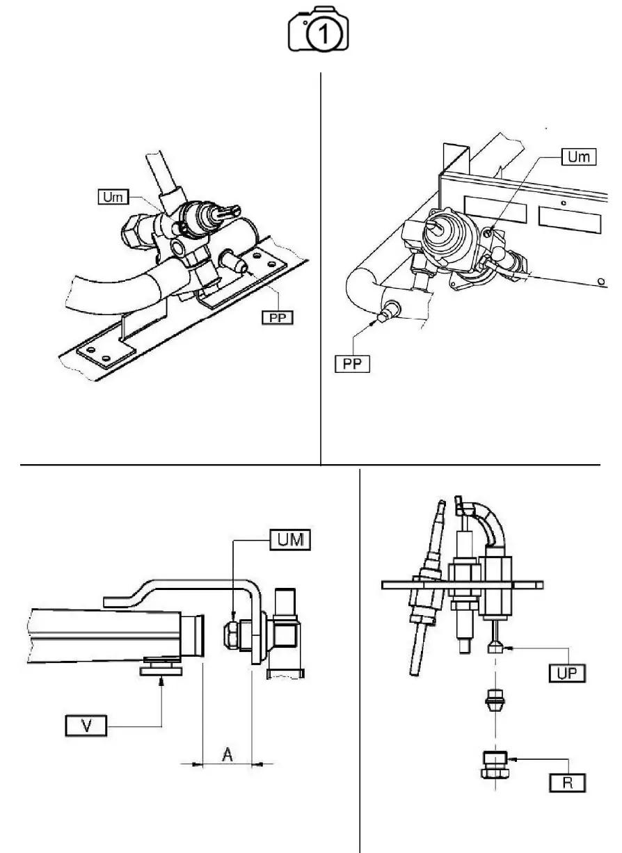
- Replace the main burner nozzle {UM).
- Adjust the main burner’s air regulator to distance A.
- Replace the pilot burner nozzle (UP).
- Adjust the pilot burner air” ow (if necessary).
- Replace the gas valve minimum nozzle (Um).
- Affix the adhesive tab indicating the new type of gas used.
- The nozzles and adhesive tabs are supplied with the appliance.
GAS FRY-TOP WITH TAP
REPLACING THE NOZZLE AND THE MAIN BURNER PRIMARY AIR REGULATION
- Remove the control panel.
- Remove nozzle UM and replace it with the one indicated in table TABl.
- Retighten nozzle UM.
- Slacken screw V and position the air regulator at distance A as indicated in table TABl.
- Retighten screw V fully.
- Reassemble all parts. For assembly, proceed in reverse order.
REPLACING THE MINIMUM ADJUSTMENT SCREW
- Remove the control panel.
- Remove nozzle UM and replace it with the one indicated in table TABl.
- Retighten nozzle UM.
- Reassemble all parts. For assembly, proceed in reverse order.
REPLACING THE PILOT BURNER NOZZLE
- Remove the control panel.
- Undo connector R.
- Remove nozzle UP and replace it with the one indicated in table TABl.
- Retighten connector R. Reassemble all parts.
- Following, in reverse order, the sequence used for their removal.
GAS GRIDDLE WITH THERMOSTATIC TAP
REPLACING THE NOZZLE AND THE MAIN BURNER PRIMARY AIR REGULATION
- Remove the control panel.
- Remove nozzle UM and replace it with the one indicated in table TABl.
- Retighten nozzle UM.
- Slacken screw V and position the air regulator at distance A as indicated in table TABl.
- Retighten screw V fully.
- Reassemble all parts. For assembly, proceed in reverse order.
REPLACING THE PILOT BURNER NOZZLE
- Remove the control panel.
- Undo connector R.
- Remove nozzle UP and replace it with the one indicated in table TABl.
- Retighten connector R. Reassemble all parts.
- Following, in reverse order, the sequence used for their removal.
COMMISSIONING
Following installation, conversion to a different type of gas or any maintenance operations, check appliance operation. In the event of any malfunction, consult the next Paragraph “Troubleshooting”.
GAS APPLIANCES
Switch on the appliance as directed in the instructions and reminders for use given in Chapter “INSTRUCTIONS FOR USE “and check:
– the gas supply pressure (see next Paragraph).
– the correct ignition of the burners and the effectiveness of the fumes removal system.
CHECKING THE GAS SUPPLY PRESSURE
- To measure the gas supply pressure use a manometer with a minimum definition of 0,1 mbar.
- Remove the control panel.
- Remove the screw from on pressure test point PP and connect the manometer to the test point.
- Make the measurement with the appliance in operation.
| IMPORTANT! IF THE GAS SUPPLY PRESSURE IS NOT WITHIN THE LIMITS (MIN. – MAX) INDICATED IN TABLE TAB2, CEASE OPERATION OF THE APPLIANCE AND CONTACT THE GAS UTILITY COMPANY. |
- Disconnect the manometer and retighten the retaining screw on the pressure connection.
ELECTRIC EQUIPMENT
Switch on the appliance as directed in the instructions and reminders for use given in Chapter “INSTRUCTIONS FOR USE” and check:
– the current values of each phase.
– the correct operation of the heating elements.
INSTRUCTIONS FOR USE
REMINDERS FOR THE USER
| READ THIS MANUAL CAREFULLY. IT PROVIDES IMPORTANT INFORMATION FOR SAFE INSTALLATION, USE AND MAINTENANCE OF THE APPLIANCE. |
| THE MANUFACTURER WILL NOT BE LIABLE FOR ANY DAMAGE OR INJURY RESULTING FROM FAILURE TO OBSERVING THE FOLLOWING RULES. |
For after-sales service, contact technical assistance centres authorized by the manufacturer and demand the use of original spare parts.
Have the appliance serviced at least twice a year.
The manufacturer recommends taking out a service contract.
The appliance is designed for professional use and must be operated by trained personnel.
The appliance is to be used for cooking food as specified in the prescriptions for use. Any other use is considered to be improper.
Do not allow the appliance to operate empty for prolonged periods. Only pre-heat the oven just before use.
Do not leave the appliance unattended while in operation.
In the event of an appliance fault or malfunction, shut the gas shut-off valve and/or switch the appliance off at the main switch installed upline.
Clean the appliance following the instructions given in Chapter” INSTRUCTIONS FOR CLEANING”
| DO NOT STORE” AM MABLE MATERIALS IN CLOSE PROXIMITY TO THE APPLIANCE. FIRE HAZARD. |
Do not obstruct any air vents or drains present on the appliance.
Do not tamper with appliance components.
Keep this manual in a safe place, known to all users, so that it can be consulted throughout the working life of the appliance.
Installation and appliance maintenance must be carried out by qualified technicians authorized by the manufacturer, in compliance with current safety standards and the instructions in this manual.
Appliance maintenance and conversion to a different type of gas must be carried out by qualified technicians authorized by the manufacturer, in compliance with current safety standards and the instructions in this manual.
USING THE GAS FRY-TOP WITH TAP
The appliance is deisgned for cooking foods directly on the hotplate (steaks, hanburgers, fish, vegetables, etc. ).
The hotplate must not be to heat pans or saucepans.
Empty the grease collection tray several times a day.
| EXERCISE GREAT CAUTION WHEN REMOVING THE TRAY. DANGER OF SCALDING FROM HOT OIL. |
BURNER IGNITION AND EXTINCTION
The gas tap control knob has the following positions:
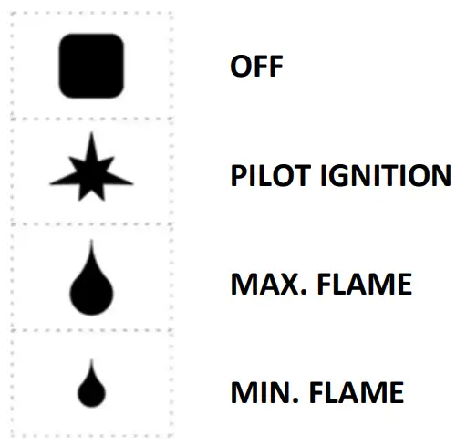
PILOT IGNITION
- Press and turn knob to “pilot on”.
- Press the knob down fully and light the pilot using the piezoelectric igniter.
- Hold the knob down for about 20 seconds before releasing it. If the pilot flame goes out, repeat the operation.
- The pilot flame can be seen through the peep hole, visible when the grease collection tray is removed.
- The pilot burner can be lit with a flame; for access, remove the grease vollection tray.
MAIN BURNER IGNITION
- To light the main burner, turn the knob from “pilot on” to “max. flame”.
- Next, depending on cooking requirements, turn the knob to any position between “max. flame ” and “min. flame”.
TURNING OFF
- To switch the main burner off, turn the knob to position “pilot on”
- To switch off the pilot flame, press and turn the knob to position “Off”.
GAS GRIDDLE WITH THERMOSTATIC TAP USE
The appliance is deisgned for cooking foods directly on the hotplate (steaks, hanburgers, fish,vegetables, etc. ).
The hotplate must not be to heat pans or saucepans.
Take particular care when using the chromed frytop.
Always clean the cooking surface and removeany food residues immediately after cooking.
While cooking, handle food only with the special scraper for the smooth fry-top or the toothed scraped for the ribbed fry-top.
The appliance is equipped with a manual reset safety thermostat that interrupts heating when the operating temperature exceeds the maximum permitted value.
Empty the grease collection tray several times a day.
| EXERCISE GREAT CAUTION WHEN REMOVING THE TRAY. DANGER OF SCALDING FROM HOT OIL. |
BURNER IGNITION AND EXTINCTION
the control knob of the thermostatic tap has the following positions use:
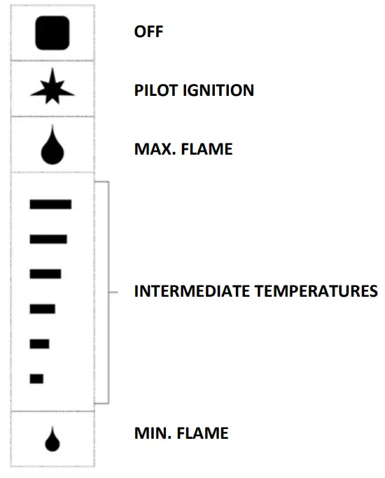
PILOT IGNITION
- Turn the knob to position “pilot on”.
- Press the knob down fully and light the pilot using the piezoelectric igniter.
- Hold the knob down for about 20 seconds before releasing it. If the pilot flame goes out, repeat the operation.
- The pilot flame can be seen through the peep hole, visible when the grease collection tray is removed.
- The pilot burner can be lit with a flame; for access, remove the grease vollection tray.
MAIN BURNER IGNITION
- Turn the knob to the chosen temperature setting for cooking.
TURNING OFF
- To switch the main burner off, turn the knob to position “pilot on”.
- To switch off the pilot flame, press and turn the knob to position “Off”
USING THE ELECTRIC FRY-TOP
The appliance is deisgned for cooking foods directly on the hotplate (steaks, hanburgers, fish, vegetables, etc. ).
The hotplate must not be to heat pans or saucepans .
Take particular care when using the chromed frytop.
Always clean the cooking surface and remove any food residues immediately after cooking .
While cooking, handle food only with the special scraper for the smooth fry-top or the toothed scraped for the ribbed fry-top.
The appliance is equipped with a manual reset safety thermostat that interrupts heating when the operating temperature exceeds the maximum permitted value.
Empty the grease collection tray several times a day.
| EXERCISE GREAT CAUTION WHEN REMOVING THE TRAY. DANGER OF SCALDING FROM HOT OIL. |
SWITCHING ON AND OFF
The thermostat control knob has the following positions:
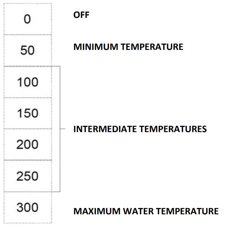
SWITCHING ON
- Turn the thermostat knob to the chosen temperature setting for cooking.
- the yellow and the green indicator lamp turn on.
- The yellow indicator light switches off when the oven reaches the set temperature.
TURNING OFF
- Turn the thermostat knob to position “0”.
- the yellow and the green indicator lamp turn off.
PROLONGED DISUSE
Before any prolonged disuse of the appliance, proceed as follows:
- Clean the appliance thoroughly.
- Rub stainless steel surfaces with a cloth soaked in vaseline oil to create a protective film.
- Close cocks or main switches ahead of the appliances.
Following prolonged disuse, proceed as follows:
- Inspect the appliance thoroughly before using it again.
- Allow electric appliances to operate at the lowest temperature for at least 60 minutes.
INSTRUCTIONS FOR CLEANING
EMINDERS FOR CLEANING
| READ THIS MANUAL CAREFULLY. IT PROVIDES IMPORTANT INFORMATION FOR SAFE INSTALLATION, USE AND MAINTENANCE OF THE APPLIANCE. |
| THE MANUFACTURER WILL NOT BE LIABLE FOR ANY DAMAGE OR INJURY RESULTING FROM FAILURE TO OBSERVING THE FOLLOWING RULES. |
| DISCONNECT THE APPLIANCE ELECTRIC SUPPLY, IF PRESENT, BEFORE CARRYING OUT ANY OPERATION. |
- Clean the satin finish stainless steel exterior surfaces, the cooking wells and the surface of the hotplates every day.
- At least twice a year, have an authorized technician clean the internal parts of the appliance.
- Do not use corrosive products to clean the floor beneath the appliance.
- Do not use direct or high pressure water jets to clean the appliance.
SATIN FINISH STAINLESS STEEL SURFACES
- Clean the surfaces with a cloth or sponge using water and proprietary non-abrasive detergents.
Follow the direction of the satin finish lines. Rinse repeatedly and dry thoroughly. - Do not use pan scourers or other iron items.
- Do not use chemical products containing chlorine.
- Do not use sharp objects which might scratch and damage the surfaces.
HOTPLATE IN DUCTILE IRON
- Clean surfaces with a damp cloth.
- Switch on for a few minutes to dry rapidly.
- Lubricate surfaces with a fine coat of food grade oil.
- Do not use pan scourers or abrasive powder detergents.
- Do not use chemical products containing chlorine.
- Do not use sharp objects which might scratch and damage the surfaces.
CHROMED HOTPLATE
- Clean the cooking surface while it is still moderatelyhot (approx. 80-100 °C). Use a cloth or sponge soaked in water and vinegar. Rinse repeatedly and dry thoroughly.
- Do not use pan scourers or abrasive powder detergents.
- Do not use chemical products containing chlorine.
- Do not use sharp objects which might scratch and damage the surfaces.
COLLECTION TRAYS
- Clean the surface, removing grease, oil, food residue etc …
INSTRUCTIONS FOR MAINTENANCE
REMINDERS FOR THE MAINTENANCE TECHNICIAN
| THE MANUFACTURER WILL NOT BE LIABLE FOR ANY DAMAGE OR INJURY RESULTING FROM FAILURE TO OBSERVING THE FOLLOWING RULES, |
Identify the specific appliance model. The model number is detailed on the packing and on the appliance dataplate.
The appliance must be installed in a well-ventilated room.
Do not obstruct any air vents or drains present on the appliance.
Do not tamper with appliance components.
Appliance maintenance and conversion to a different type of gas must be carried out by qualified technicians authorized by the manufacturer, in compliance with current safety standards and the instructions in this manual.
CONVERSION TO ANOTHER TYPE OF GAS
See Chapter” Instructions for installation “.
COMMISSIONING
See Chapter” Instructions for installation “.
TROUBLESHOOTING
GAS FRY-TOP WITH TAP
Possible causes:
- Insufficient gas supply pressure.
- Blocked tubing or nozzle.
- Defective gas tap or valve.
- Igniter defective or not properly connected.
- Igniter or igniter wire defective.
PILOT BURNER GOES OUT DURING USE.
Possible causes:
- Insufficient gas supply pressure.
- Defective gas tap or valve.
- Defective thermocouple or insufficient heating.
- Thermocouple incorrectly connected to gas tap or valve.
Knob of gas tap or valve not pressedsufficiently.
THE MAIN BURNER DOES NOT LIGHT (EVEN THOUGH PILOT IS LIT).
Possible causes:
- Insufficient gas supply pressure.
- Blocked tubing or nozzle.
- Defective gas tap or valve.
- Defective burner (gas outlet holes clogged).
HEATING CANNOT BE ADJUSTED.
Possible causes:
- Defective gas valve.
GAS GRIDDLE WITH THERMOSTATIC TAP THE PILOT BURNER DOES NOT LIGHT.
Possible causes:
- Insufficient gas supply pressure.
- Blocked tubing or nozzle.
- Defective gas tap or valve.
- Igniter defective or not properly connected.
- Igniter or igniter wire defective.
PILOT BURNER GOES OUT DURING USE.
Possible causes:
- Insufficient gas supply pressure.
- Defective gas tap or valve.
- Defective thermocouple or insufficient heating.
- Thermocouple incorrectly connected to gas tap or valve.
Knob of gas tap or valve not pressedsufficiently.
THE MAIN BURNER DOES NOT LIGHT (EVEN THOUGH PILOT IS LIT).
Possible causes:
- Insufficient gas supply pressure.
- Blocked tubing or nozzle.
- Defective gas tap or valve.
- Defective burner (gas outlet holes clogged).
HEATING CANNOT BE ADJUSTED.
Possible causes:
- Defective gas valve.
ELECTRIC FRY-TOP
THE APPLIANCE DOES NOT HEAT.
Possible causes:
- Temperature thermostat defective.
- Heating elements defective.
- Safety thermostat tripped.
HEATING CANNOT BE ADJUSTED.
Possible causes:
- Temperature thermostat defective.
REPLACING COMPONENTS
REMINDERS FOR REPLACING COMPONENTS
| SHUT THE GAS SHUT-OFF VALVE AND/OR SWITCH THE APPLIANCE OFF AT THE MAIN SWITCH INSTALLED UPSTREAM. |
| AFTER REPLACING A GAS SYSTEM COMPONENT, CHECK FOR GAS LEAKS AT CONNECTION POINTS. |
| DISCONNECT THE APPLIANCE ELECTRIC SUPPLY, IF PRESENT, BEFORE CARRYING OUT ANY OPERATION. |
| AFTER REPLACING AN ELECTRICAL SYSTEM COMPONENT, CHECK IT IS CORRECTLY WIRED. |
GAS FRY-TOP WITH TAP
REPLACING THE GAS TAP.
- Remove the control panel.
- Remove and replace the component.
- Reassemble all parts. For assembly, proceed in reverse order.
REPLACING THE BURNER, THE PILOT BURNER, THE THERMOCOUPLE, THE PIEZOELECTRIC IGNITIONAND THE IGNITER
- Remove the control panel.
- Remove and replace the component.
- Reassemble all parts. For assembly, proceed inreverse order.
GAS GRIDDLE WITH THERMOSTATIC TAP
THERMOSTATIC TAP SUBSTITUTION
- Remove the control panel.
- Remove the bulb from its seat on the bottom of the hotplate.
- Remove and replace the component.
- Insert the bulb properly in its seat on the bottom of the hotplate.
- Reassemble all parts. For assembly, proceed in reverse order.
REPLACING THE BURNER, THE PILOT BURNER, THE THERMOCOUPLE, THE PIEZOELECTRIC IGNITION AND THE IGNITER
- Remove the control panel.
- Remove and replace the component.
- Reassemble all parts. For assembly, proceed in reverse order.
ELECTRIC FRY-TOP
REPLACING THE HEATING AND LIGHT GLOWS.
- Remove the control panel.
- Remove and replace the component.
- Reassemble all parts. For assembly, proceed in reverse order.
REPLACING THE WORKING THERMOSTAT AND SAFETY THERMOSTAT
- Remove the control panel.
- Remove the bulb from its seat on the bottom of the hotplate.
- Remove and replace the component.
- Insert the bulb properly in its seat on the bottom of the hotplate.
- Reassemble all parts. For assembly, proceed in reverse order.
CLEANING THE INTERIOR
Check the condition of the inside of the appliance.
Remove any built-up dirt.
Check and clean the fumes exhaust system.
MAIN COMPONENTS
GAS FRY-TOP WITH TAP
- GAS COCK
- MAIN BURNER
- Pilot burner
- Thermocouple
- Igniter
- Piezoelectric ignition
GAS GRIDDLE WITH THERMOSTATIC TAP
- Thermostatic tap
- MAIN BURNER
- Pilot burner
- Thermocouple
- Piezoelectric ignition
- Igniter
ELECTRIC FRY-TOP
- Working thermostat
- Safety thermostat
- Heating element
- Indicator light
INSTALLATION DIAGRAM

TECHNICAL DATA
Nozzles and Settings
| TAB1 | |||||
| Gas Gaz | Pa (mbar) | UM UP A | 60/30 FT..G
60/60 FT..G | 65/40 – 70/40 FT..G | 90/40 FT..G
90/80 FT..G |
| 65/70 – 70/70 FT..G | |||||
| G20 G20/G25 | 20 20/25 | UM | 165 | 185 | 200L |
| UP | 36 | 36 | 36 | ||
| A (mm) | 25 | 25 | 0,5 | ||
| Um | REG | REG | REG | ||
| G25 | 20 | UM | 185 | 200 | 215L |
| UP | 36 | 36 | 36 | ||
| A (mm) | 25 | 25 | 0,5 | ||
| Um | REG | REG | REG | ||
| G25 | 25 | UM | 175 | 185 | 200L |
| UP | 36 | 36 | 36 | ||
| A (mm) | 25 | 25 | 0,5 | ||
| Um | REG | REG | REG | ||
| G20 | 25 | UM | |||
| UP | |||||
| A (mm) | |||||
| Um | |||||
| G25.1 | 25 | UM | |||
| UP | |||||
| A (mm) | |||||
| Um | |||||
| G30/G31 | 28-30/37 28-30 | UM | 120 | 120 | 135L |
| UP | 19 | 19 | 19 | ||
| A (mm) | 12 | 12 | – | ||
| Um | 70 | 70 | 100 | ||
| G30/G31 | 37 | UM | |||
| UP | |||||
| A (mm) | |||||
| Um | |||||
| G30/G31 | 50 | UM | 105 | 110 | 120L |
| UP | 19 | 36 | 19 | ||
| A (mm) | 12 | 10 | – | ||
| Um | 70 | 70 | 100 | ||
| G110 | 8 | UM | |||
| UP | |||||
| A (mm) | |||||
| Um | |||||
| G120 | 8 | UM | |||
| UP | |||||
| A (mm) | |||||
| Um | |||||
| Pa :Supply pressure | |||||
| UM :MAX nozzle | |||||
| Um : MIN nozzle | |||||
| UP : Pilot | |||||
| A :Aerator Opening | |||||
| REG : Regulated | |||||
Categories and pressures
| Paese Land Country Pays Pais | Category | Gas-Gaz | Supply pressure | ||
| Normal | Min. | Max | |||
| LU-PL | 12E | G20 | 20 | 17 | 25 |
| NO | 12H | G20 | 20 | 17 | 25 |
| NL | 12L | G25 | 25 | 20 | 30 |
| LU | 13+ | G30/G31 | 28-30/37 | 20/25 | 35/45 |
| NO-NL-CY-MT | 13B/P | G30/G31 | 28-30 | 25 | 35 |
| PL | 13B/P | G30/G31 | 37 | 25 | 45 |
| BE-FR | 112E+3+ | G20/G31 | 20/25 | 17 | 25/30 |
| G30/G31 | 28-30/37 | 20/25 | 35/45 | ||
| DE | 112ELL3B/P | G20 | 20 | 17 | 25 |
| G25 | 20 | 18 | 25 | ||
| G30/G31 | 50 | 42.5 | 57.5 | ||
| ES-GB-GR-1E-1T-PT-SK | 112H3+ | G20 | 20 | 17 | 25 |
| G30/G31 | 28-30/37 | 20/25 | 35/45 | ||
| F1-BG-EE-LV-LT-CZ-S1-TR-HR-RO | 112H3B/P | G20 | 20 | 17 | 25 |
| G30/G31 | 28-30 | 25 | 35 | ||
| AT-CH | 112H3B/P | G20 | 20 | 17 | 25 |
| G30/G31 | 50 | 42.5 | 57.5 | ||
| HU | 112HS3B/P | G20 | 25 | 18 | 33 |
| G25.1 | 25 | 18 | 33 | ||
| G30/G31 | 28-30 | 25 | 35 | ||
| HU | 112HS3B/P | G20 | 25 | 18 | 33 |
| G25.1 | 25 | 18 | 33 | ||
| G30/G31 | 50 | 42.5 | 57.5 | ||
|
SE |
1111ab2H3B/P | G20 | 20 | 17 | 25 |
| G30/G31 | 28-30 | 25 | 35 | ||
| G110 | 8 | 6 | 15 | ||
| G120 | 8 | 6 | 15 | ||
| DK | 1111a2H3B/P | G20 | 20 | 17 | 25 |
| G30/G31 | 28-30 | 25 | 35 | ||
| G110 | 8 | 6 | 15 | ||
| 1T-CH | 111a2H | G20 | 20 | 17 | 25 |
| G110 | 8 | 6 | 15 | ||
Technical data of gas appliances
| TAB.3 | ||||||||||||
| Models | Width | IQn | Total gas consumption | |||||||||
| G20 (20) | G25 (25) | G25 (20) | G20 (25) | G25.1 (25) | G110 (8) | G120 (8) | G30 (29) | G30 (37) | G30 (50) | |||
| mm | kW | m3/h | m3/h | m3/h | m3/h | m3/h | m3/h | m3/h | Kg/h | Kg/h | Kg/h | |
| _60/30 FT.G. | 300 | 5.2 | 0.55 | 0.64 | 0.64 | 0.55 | 0.639 | 0.41 | 0.41 | 0.41 | ||
| _60/60 FT.G. | 600 | 10.4 | 1.101 | 1.28 | 1.28 | 1.101 | 1.278 | 0.82 | 0.82 | 0.82 | ||
| _60/30 FT.G.CR | 300 | 5.2 | 0.55 | 0.64 | 0.64 | 0.55 | 0.639 | 0.41 | 0.41 | 0.41 | ||
| _60/60 FT.G.CR | 600 | 10.4 | 1.101 | 1.28 | 1.28 | 1.101 | 1.278 | 0.82 | 0.82 | 0.82 | ||
| _65/40 FT.G. | 400 | 5.7 | 0.603 | 0.702 | 0.702 | 0.603 | 0.7 | 0.45 | 0.45 | 0.45 | ||
| _65/70 FT.G. | 700 | 11.4 | 1.206 | 1.403 | 1.403 | 1.206 | 1.401 | 0.899 | 0.899 | 0.899 | ||
| _65/40 FT.G.CR | 400 | 5.7 | 0.603 | 0.702 | 0.702 | 0.603 | 0.7 | 0.45 | 0.45 | 0.45 | ||
| _65/70 FT.G.CR | 700 | 11.4 | 1.206 | 1.403 | 1.403 | 1.206 | 1.401 | 0.899 | 0.899 | 0.899 | ||
| _70/40 FT.G. | 400 | 5.7 | 0.60 | 0.70 | 0.70 | 0.60 | 0.70 | 0.45 | 0.45 | 0.45 | ||
| _70/70 FT.G. | 700 | 11.4 | 1.21 | 1.40 | 1.40 | 1.21 | 1.40 | 0.90 | 0.90 | 0.90 | ||
| _70/40 FT.G.CR. | 400 | 5.7 | 0.60 | 0.70 | 0.70 | 0.60 | 0.70 | 0.45 | 0.45 | 0.45 | ||
| _70/70 FT.G.CR. | 700 | 11.4 | 1.21 | 1.40 | 1.40 | 1.21 | 1.40 | 0.90 | 0.90 | 0.90 | ||
| _90/40 FT.G. | 400 | 6.9 | 0.73 | 0.85 | 0.85 | 0.73 | 0.85 | 0.54 | 0.54 | 0.54 | ||
| _90/80 FT.G. | 800 | 13.8 | 1.46 | 1.70 | 1.70 | 1.46 | 1.70 | 1.09 | 1.09 | 1.09 | ||
| _90/40 FT.G.CR. | 400 | 6.9 | 0.73 | 0.85 | 0.85 | 0.73 | 0.85 | 0.54 | 0.54 | 0.54 | ||
| _90/80 FT.G.CR. | 800 | 13.8 | 1.46 | 1.70 | 1.70 | 1.46 | 1.70 | 1.09 | 1.09 | 1.09 | ||
Technical data of electric appliances
| TAB.4 | ||||||
| Models | Width | Power supply voltage | Phases | Frequency | Max. total power | Power supply cable section |
| mm | V | N. | Hz | kW | ||
| _60/30 FT…E… | 300 | 380-415 | 3N | 50-60 | 3 | 5G1 |
| 220-240 | 1N | 50-60 | 3 | 3G1.5 | ||
| _60/60 FT…E. | 600 | 380-415 | 3N | 50-60 | 6 | 5G1.5 |
| 220-240 | 1N | 50-60 | 6 | 3G4 | ||
| _60/30 FT…E.-D | 300 | 380-415 | 3N | 50-60 | 3 | 5G1 |
| _60/60 FT…E.-D | 600 | 380-415 | 3N | 50-60 | 6 | 5G1.5 |
| _65/40 FT.E. | 400 | 380-415 | 3N | 50-60 | 4.5 | 5G1 |
| _65/70 FT.E. | 700 | 380-415 | 3N | 50-60 | 9 | 5G1.5 |
| _65/40 FT.E.-D | 400 | 380-415 | 3N | 50-60 | 4.5 | 5G1 |
| 220-240 | 3 | 50-60 | 4.5 | 4G1.5 | ||
| _65/70 FT.E.-D | 700 | 380-415 | 3N | 50-60 | 9 | 5G1.5 |
| 220-240 | 3 | 50-60 | 9 | 4G2.5 | ||
| _70/40 FT.E… | 400 | 380-415 | 3N | 50-60 | 5.40 | 5G1 |
| _70/80 FT…E… | 800 | 380-415 | 3N | 50-60 | 10.80 | 5G1.5 |
| _90/40 FT…E. | 400 | 380-415 | 3N | 50-60 | 7.50 | 5G1.5 |
| _90/80 FT…E. | 800 | 380-415 | 3N | 50-60 | 15.00 | 5G2.5 |